SI-F130 Manual(EN)_jpg_ Rev1.pdf - 第116页
Adjustment of FF/FR Axis Feed R oller Y -Direction Position HLF-10408-01 Adjustment of FF/FR Axis Feed Roller Y -Direction Position SHEET 1/2 Adjustment of FF/FR Axis Fe ed Roller Y -Direction Position [Necessary jigs] •…
Adjustment of FF/FR Axis Belt Tension
HLF-10407-01
Adjustment of FF/FR Axis Belt
Tension
SHEET
3/3
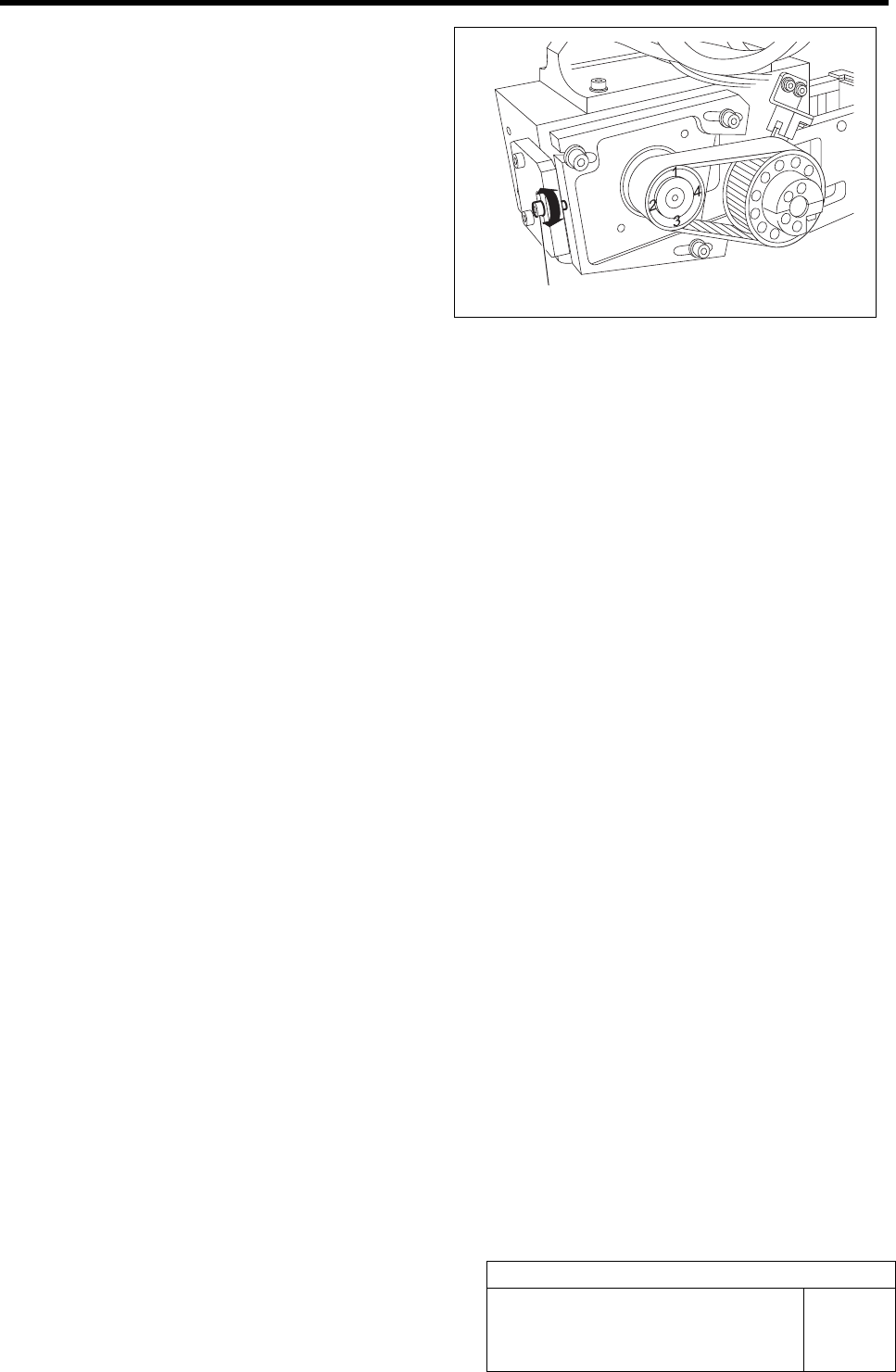
7 Adjust the belt tension by turning the tension
adjustment screw so that the maximum
value of the tension measured in the pro-
cedure 6 is within the standard.
Standard: 6 kgf < Maximum value < 7 kgf
(Target:6.8 kgf)
8 After adjusting the tension, retighten the cap screws (3-M4) on the F axis motor mounting bracket to
secure the bracket.
9 Remove the tension block jig.
Tension adjustment screw
Adjustment of FF/FR Axis Feed Roller Y-Direction Position
HLF-10408-01
Adjustment of FF/FR Axis Feed
Roller Y-Direction Position
SHEET
1/2
Adjustment of FF/FR Axis Feed Roller Y-Direction Position
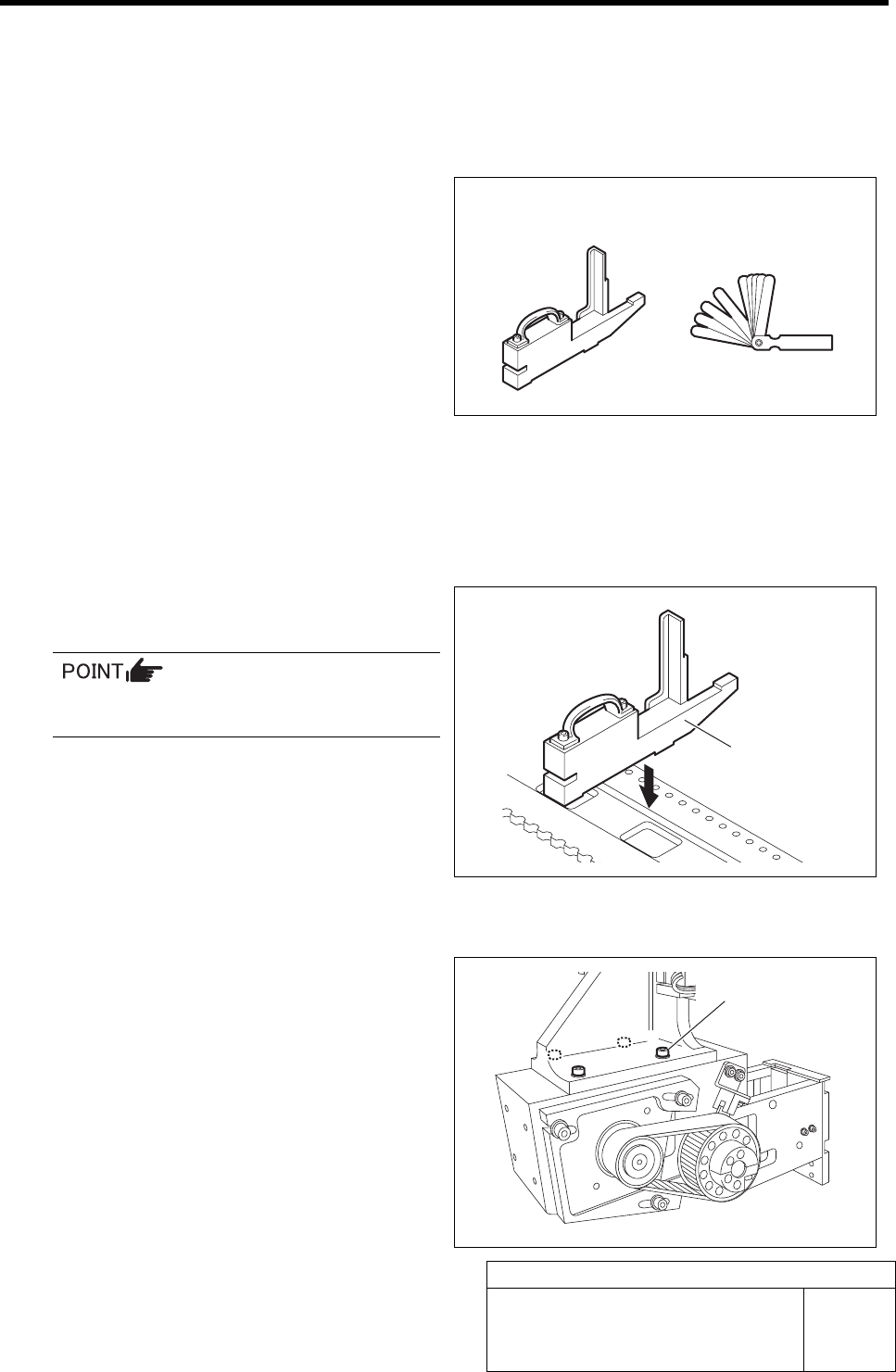
[Necessary jigs]
• Feed adjusting jig
• Thickness gauge
[Procedure]
1 Move the X axis to a position approximately
10 cm right from the position of No.20 on the
cassette table.
2 Set the feed adjusting jig to the No.20 posi-
tion on the cassette table.
There should be no gap between the feed
adjusting jig and the cassette table.
3 Move the X axis by hand to move the feed
body to the top of the feed adjusting jig.
4 Loosen the cap screws (4-M4) fastening the
feed body.
Feed adjusting jig Thickness gauge
Feed adjusting jig
Cap screw
Adjustment of FF/FR Axis Feed Roller Y-Direction Position
HLF-10408-01
Adjustment of FF/FR Axis Feed
Roller Y-Direction Position
SHEET
2/2
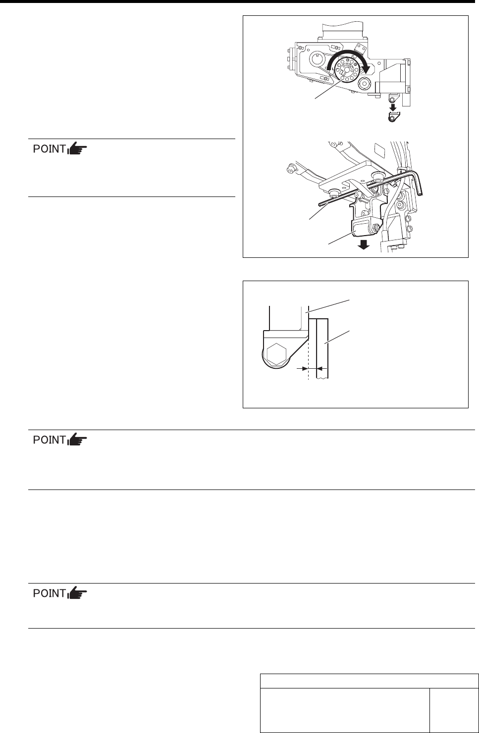
5 Lower the feed roller by hand, and insert a
2.5 mm wrench for fixing.
1. Turn the driven pulley on the feed
body by hand clockwise to lower the
feed roller.
2. Insert a 2.5 mm wrench into the
bracket of the feed roller to hold the
feed roller at the lowering position.
For the driven pulleys for both of the FF
axis/FR axis, lower the feed roller by
turning clockwise.
6 Make adjustment so that the clearance be-
tween the feed roller bracket and feed ad-
justing jig is 0 to 0.1 mm in Y-direction.
1. Move the feed body to adjust so that
the feed roller bracket and feed ad-
justing jig is 0 to 0.1 mm in Y-direction.
2. Check that the narrowest clearance
between the feed roller bracket and
feed adjusting jig is within a range of 0
to 0.1 mm by using thickness gauge.
• The feed roller should not contact the feed adjusting jig.
• The feed adjusting jig should not float (thickness gauge of t= 0.01 mm should not be inserted
between the feed adjusting jig and cassette table.)
7 After adjusting the clearance, retighten the feed body fixing cap screws (4-M4) to fix the feed body.
8 Recheck the clearance between the feed roller brackets and feed adjusting jig.
9 For No.1 and 40 positions on the cassette table, also check that the clearance between the feed
roller bracket and the feed adjusting jig is 0 to 0.1 mm.
If the clearances at No.1 and 40 on the cassette table are out of the range of 0 to 0.1 mm, re-
adjust from the No.20 position.
Feed roller bracket
Feed adjusting jig
0 to 0.1 mm
Driven pulley
2.5 mm Wrench
Feed roller