SI-F130 Manual(EN)_jpg_ Rev1.pdf - 第117页
Adjustment of FF/FR Axis Feed R oller Y -Direction Position HLF-10408-01 Adjustment of FF/FR Axis Feed Roller Y -Direction Position SHEET 2/2 5 Lower the feed roller by hand, and insert a 2.5 mm wrench for fixing. 1. T u…
Adjustment of FF/FR Axis Feed Roller Y-Direction Position
HLF-10408-01
Adjustment of FF/FR Axis Feed
Roller Y-Direction Position
SHEET
1/2
Adjustment of FF/FR Axis Feed Roller Y-Direction Position
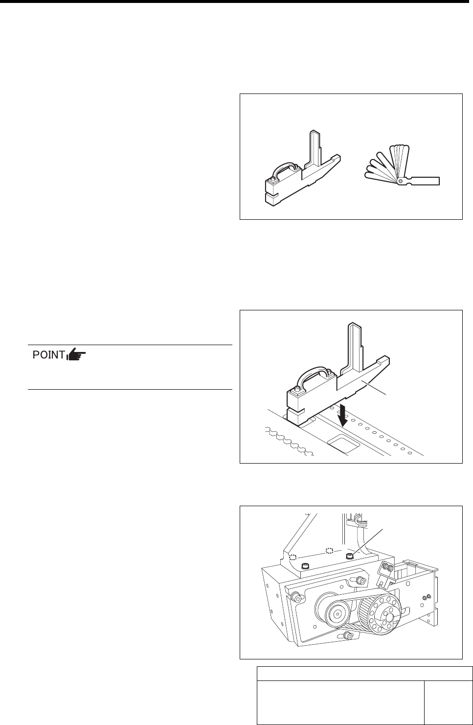
[Necessary jigs]
• Feed adjusting jig
• Thickness gauge
[Procedure]
1 Move the X axis to a position approximately
10 cm right from the position of No.20 on the
cassette table.
2 Set the feed adjusting jig to the No.20 posi-
tion on the cassette table.
There should be no gap between the feed
adjusting jig and the cassette table.
3 Move the X axis by hand to move the feed
body to the top of the feed adjusting jig.
4 Loosen the cap screws (4-M4) fastening the
feed body.
Feed adjusting jig Thickness gauge
Feed adjusting jig
Cap screw
Adjustment of FF/FR Axis Feed Roller Y-Direction Position
HLF-10408-01
Adjustment of FF/FR Axis Feed
Roller Y-Direction Position
SHEET
2/2
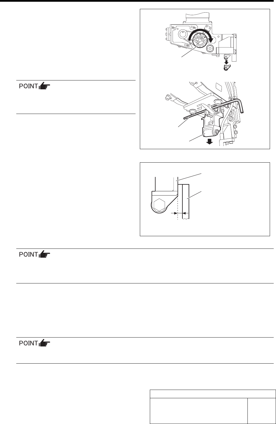
5 Lower the feed roller by hand, and insert a
2.5 mm wrench for fixing.
1. Turn the driven pulley on the feed
body by hand clockwise to lower the
feed roller.
2. Insert a 2.5 mm wrench into the
bracket of the feed roller to hold the
feed roller at the lowering position.
For the driven pulleys for both of the FF
axis/FR axis, lower the feed roller by
turning clockwise.
6 Make adjustment so that the clearance be-
tween the feed roller bracket and feed ad-
justing jig is 0 to 0.1 mm in Y-direction.
1. Move the feed body to adjust so that
the feed roller bracket and feed ad-
justing jig is 0 to 0.1 mm in Y-direction.
2. Check that the narrowest clearance
between the feed roller bracket and
feed adjusting jig is within a range of 0
to 0.1 mm by using thickness gauge.
• The feed roller should not contact the feed adjusting jig.
• The feed adjusting jig should not float (thickness gauge of t= 0.01 mm should not be inserted
between the feed adjusting jig and cassette table.)
7 After adjusting the clearance, retighten the feed body fixing cap screws (4-M4) to fix the feed body.
8 Recheck the clearance between the feed roller brackets and feed adjusting jig.
9 For No.1 and 40 positions on the cassette table, also check that the clearance between the feed
roller bracket and the feed adjusting jig is 0 to 0.1 mm.
If the clearances at No.1 and 40 on the cassette table are out of the range of 0 to 0.1 mm, re-
adjust from the No.20 position.
Feed roller bracket
Feed adjusting jig
0 to 0.1 mm
Driven pulley
2.5 mm Wrench
Feed roller
Adjustment of FF/FR Axis Feed Roller Height
HLF-10409-01
Adjustment of FF/FR Axis Feed
Roller Height
SHEET
1/2
Adjustment of FF/FR Axis Feed Roller Height
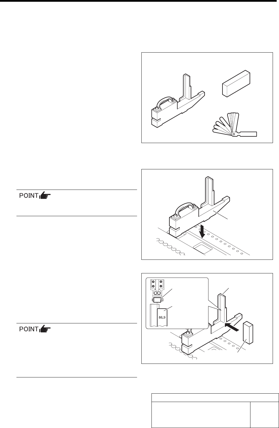
[Necessary jigs]
• Feed adjusting jig
• Part feed height jig
• Thickness gauge
[Procedure]
1 Set the feed adjusting jig to the No.20 posi-
tion on the cassette table.
There should be no clearance between the
feed adjusting jig and the cassette table.
2 Place a part feed height jig on the feed ad-
justing jig.
3 Adjust the position of the part feed height jig
so that the part feed height jig end face
matches the center of the feed roller.
The cassette feed lever is fed in the center
of the roller, however, the roller tends to be
fed in the above right direction, then, ad-
just the position of the part feed height jig
between the jig end face and the roller
center.
Feed adjusting jig
Part feed height jig
Thickness gauge
Feed adjusting jig
Feed adjusting jig
Part feed height jig
Feed roller
Part feed
height jig