SI-F130 Manual(EN)_jpg_ Rev1.pdf - 第135页
Adjustment of Plunger Upper/Lower Backward Detect S ensor HLF-10416-01 Adjustment of Plunger Uppe r/Low er Backward Detect Sensor SHEET 2/2 4 Check the LED lighting-on st ate of the plunger return sensor (Upp er/Lower). …
Adjustment of Plunger Upper/Lower Backward Detect Sensor
HLF-10416-01
Adjustment of Plunger Upper/Lower
Backward Detect Sensor
SHEET
1/2
Adjustment of Plunger Upper/Lower Backward Detect Sensor
[Necessary jigs]
• Thickness gauge
[Procedure]
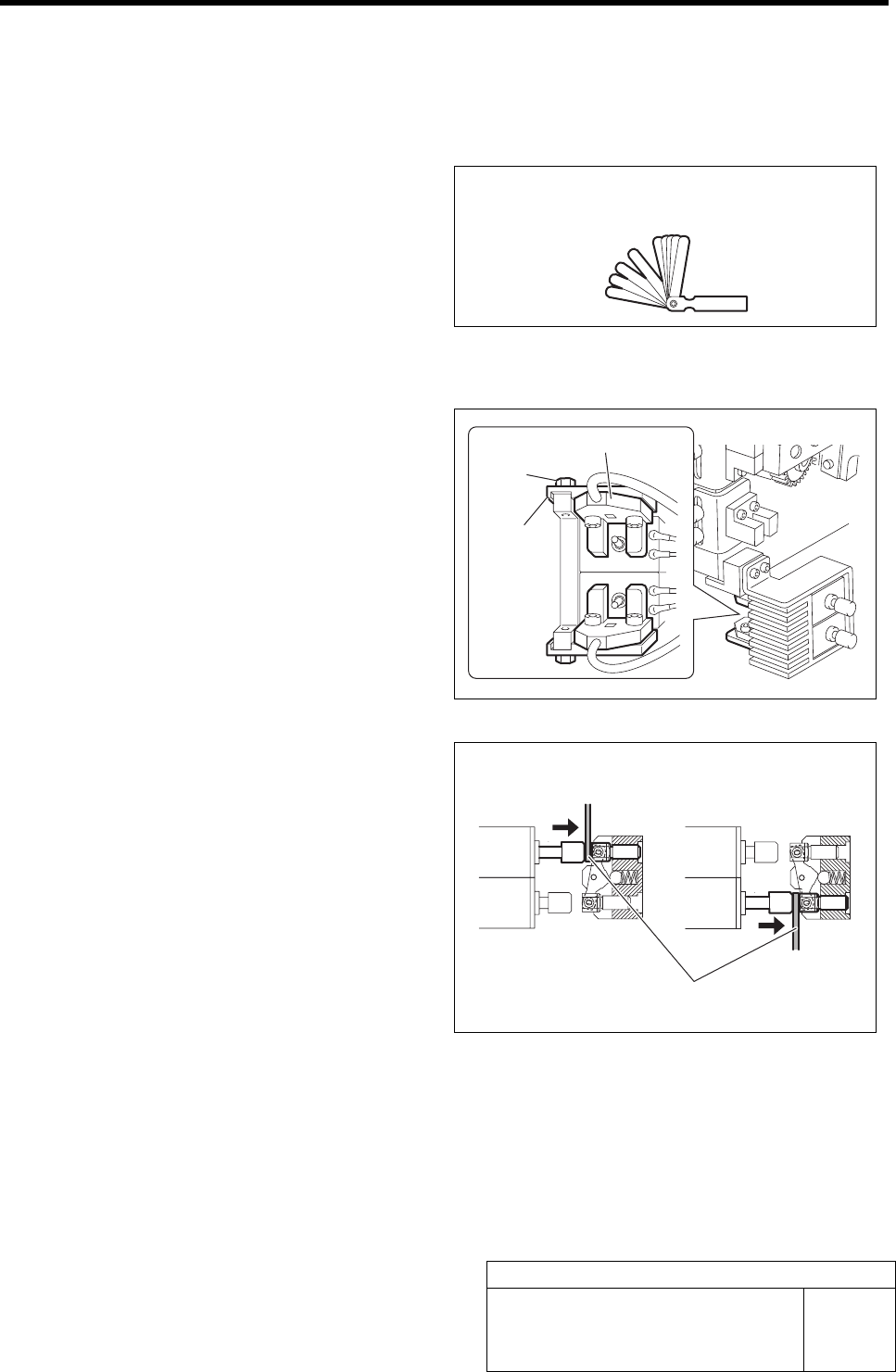
1 Loosen the bolts fastening the mounting
bracket for the plunger return sensor.
2 Adjust the LED extinguishing position of the
plunger return sensor (Upper/Lower).
1. Press in the mechanical valve.
2. Pull out the plunger by hand, and
pinch a thickness gauge of t=1.0 mm
between the plunger and mechanical
valve.
3. Move the bracket to adjust the sensor
position so that the LED for the
plunger return sensor extinguishes in
this state.
3 Fasten the bolts for the mounting bracket to fix the plunger return sensor.
Thickness gauge
Bolt
Bracket
Upper Lower
Thickness gauge
Plunger return sensor

Adjustment of Plunger Upper/Lower Backward Detect Sensor
HLF-10416-01
Adjustment of Plunger Upper/Lower
Backward Detect Sensor
SHEET
2/2
4 Check the LED lighting-on state of the plunger return sensor (Upper/Lower).
1. Press in the mechanical valve.
2. Pull out the plunger by hand, and pinch a thickness gauge of t=1.2 mm between the plunger
and the mechanical valve.
3. Check that the LED for the plunger return sensor lights up in this state.
<Thickness of thickness gauge and state of sensor LED>
Thickness of thickness gauge State of LED for plunger return
sensor
1.0 mm Extinguish
1.2 mm Lights-up
Non (Origin position) Lights-up
Nozzle Omission Detection Sensor Position Adjustment
HLF-10417-01
Nozzle Omission Detection Sensor
Position Adjustment
SHEET
1/4
Nozzle Omission Detection Sensor Position Adjustment
[Necessary jigs]
• Nozzle jig (AF06040)
• Thickness gauge (t=1.0 mm)
[Procedure]
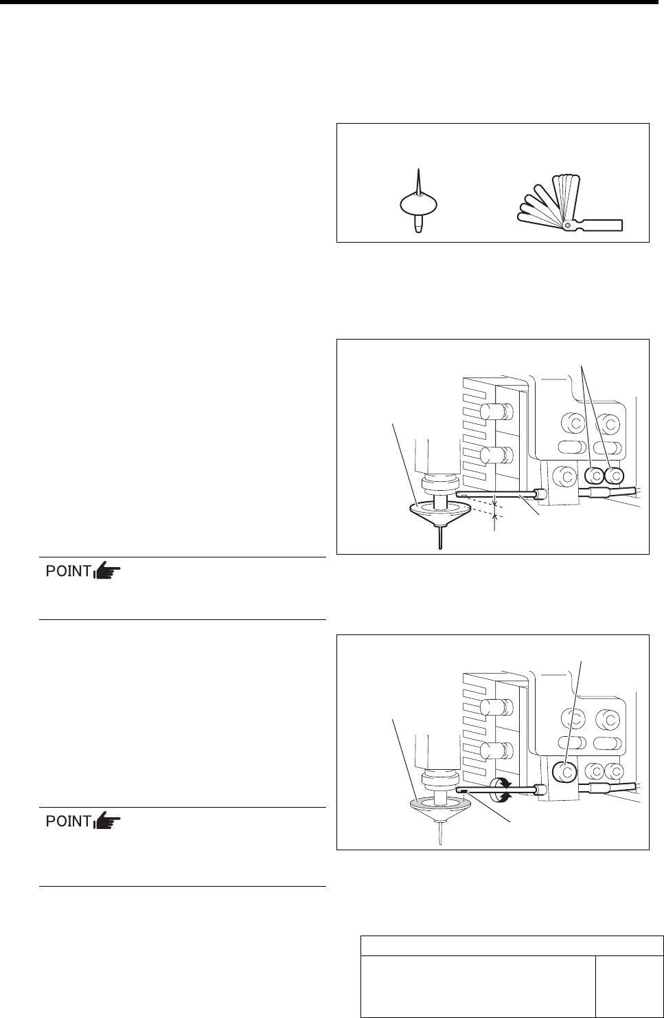
1 Install the nozzle jig (AF06040) to the turret
No.1.
2 Adjust the clearance between the nozzle
omission detection sensor and the upper
face of the nozzle reflector to 1.0 mm.
1. Loosen the cap screw for the nozzle
omission detection sensor.
2. Adjust with thickness gauge so that
clearance between the end of the noz-
zle omission detection sensor and the
upper face of the reflector is 1.0 mm.
3. Tighten the cap screw.
Fiber sensor is used in the nozzle omission
detection sensor.
3 Adjust the optical axis of the nozzle omission
detection sensor.
1. Loosen the split fastening screw fixing
the nozzle omission detection sensor.
2. Turn the nozzle omission detection
sensor to adjust so that the sensor lu-
minescence part is directed to reflector
plane of the nozzle jig (AF06040).
Optical axis can be easily adjusted by
slightly widening the split fastening part
of the bracket using flat end screwdriver.
3. Tighten the split fastening screw.
Nozzle jig (AF06040)
Thickness gauge
Cap screw
Nozzle omission
detection sensor
1.0 mm
Nozzle jig
(AF06040)
Reflector plane part
Split fastening screw
Sensor luminescence part