SI-F130 Manual(EN)_jpg_ Rev1.pdf - 第140页
Phase Adjustment for Nozzle HLF-10418-01 Phase A djust ment for Nozzle SHEET 1/8 Phase Adjustment for Nozzle [Necessary jigs] • Phase adjusting jig for nozzle • Phase adjusting jig [Procedure] 1 T urn OFF the V ACUUM bre…
Nozzle Omission Detection Sensor Position Adjustment
HLF-10417-01
Nozzle Omission Detection Sensor
Position Adjustment
SHEET
4/4
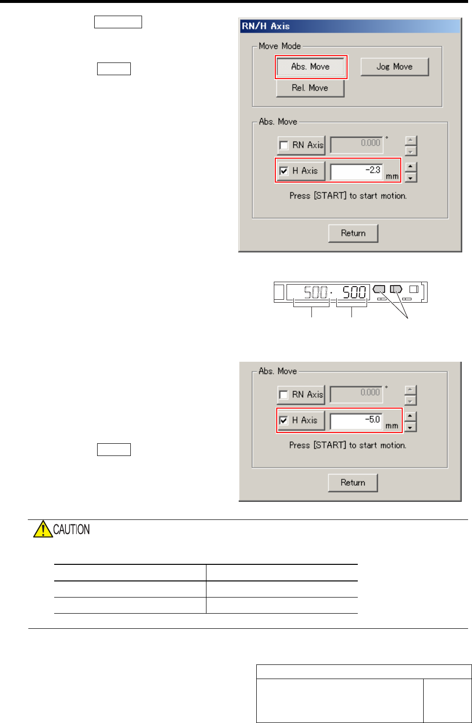
2. Click the Abs. Move button.
3. Click the check box for H axis and put
check in it to input “-2.3”.
4. Press the START button on the opera-
tion panel.
H axis lowers to a position of -2.3 mm.
5. Check the present light receiving
value with the nozzle omission detec-
tion sensor amplifier, and set its value
to the threshold.
Example: If the light receiving value is “500”, set
the threshold to”500”.
7 Check that the sensor is turned off at a posi-
tion where H axis is lowered by -5.0 mm.
1. On the RN/H Axis screen, click check
box for H axis and put check in it to
input “-5.0”.
2. Press the START button on the opera-
tion panel.
H axis lowers to a position of -5.0 mm.
3. Check that the sensor is turned off.
Do not confuse the lowering dimension when checking sensor OFF and the lowering dimension for
setting threshold.
Item H Axis lowering dimension
Threshold setting -2.3 mm
Sensor OFF check -5.0 mm
Light receiving value = Threshold
UP/DOWN button
Phase Adjustment for Nozzle
HLF-10418-01
Phase Adjustment for Nozzle
SHEET
1/8
Phase Adjustment for Nozzle
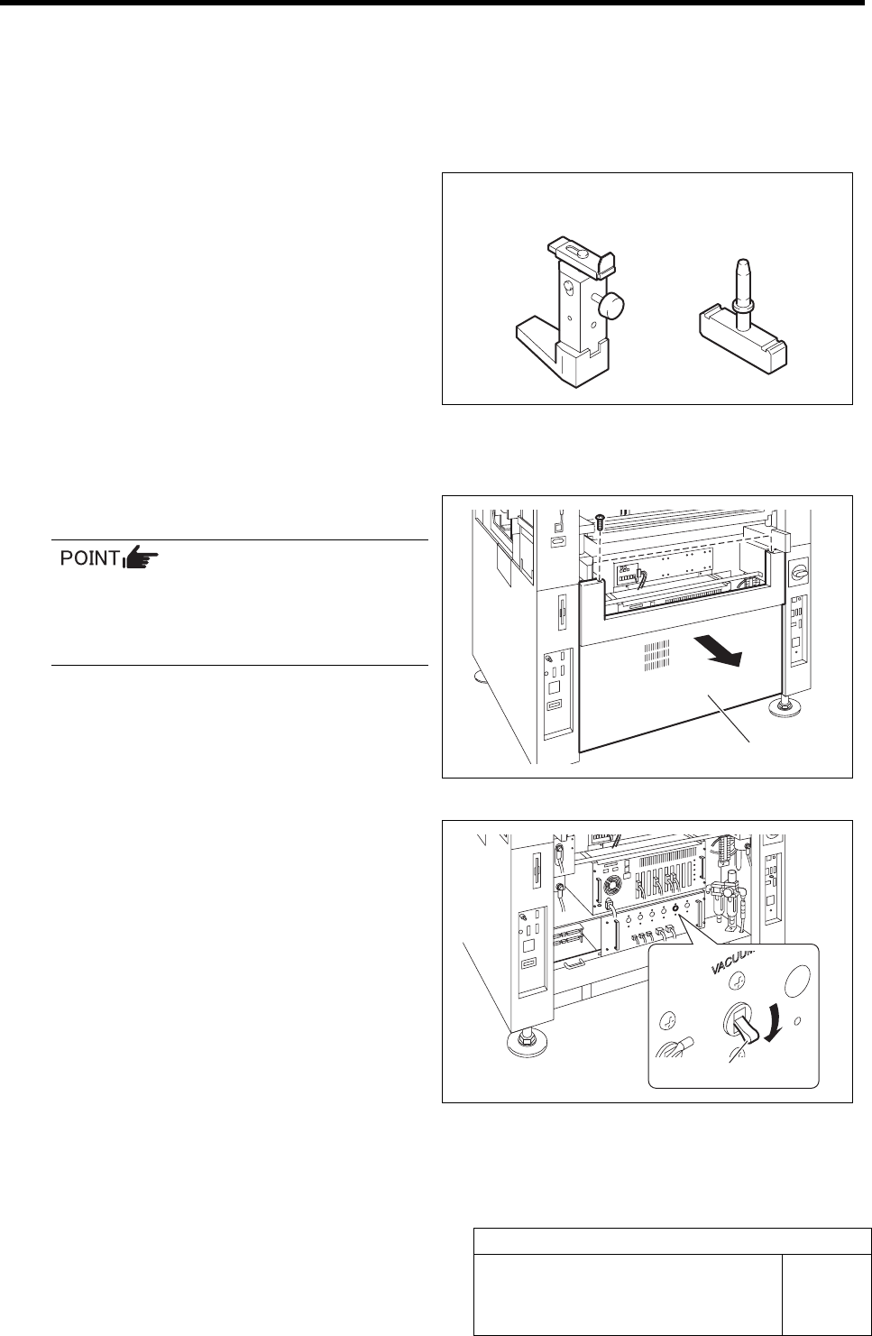
[Necessary jigs]
• Phase adjusting jig for nozzle
• Phase adjusting jig
[Procedure]
1 Turn OFF the VACUUM breaker.
In order to prevent suction of contaminant
and dust from mechanical valve, turn OFF
the VACUUM breaker before removing the
mechanical valve.
1. Loosen 2 screws to remove the lower
panel on the front of the unit.
2. Turn OFF the VACUUM breaker in
the PC unit.
Lower panel
VACUUM breaker
Phase adjusting jig
for nozzle
Phase adjusting jig
Phase Adjustment for Nozzle
HLF-10418-01
Phase Adjustment for Nozzle
SHEET
2/8
2 Remove all of the mechanical valves.
1. Loosen 2 cap screws to remove the
mechanical valve.
2. Manually turn the turret and remove
the mechanical valves sequentially.
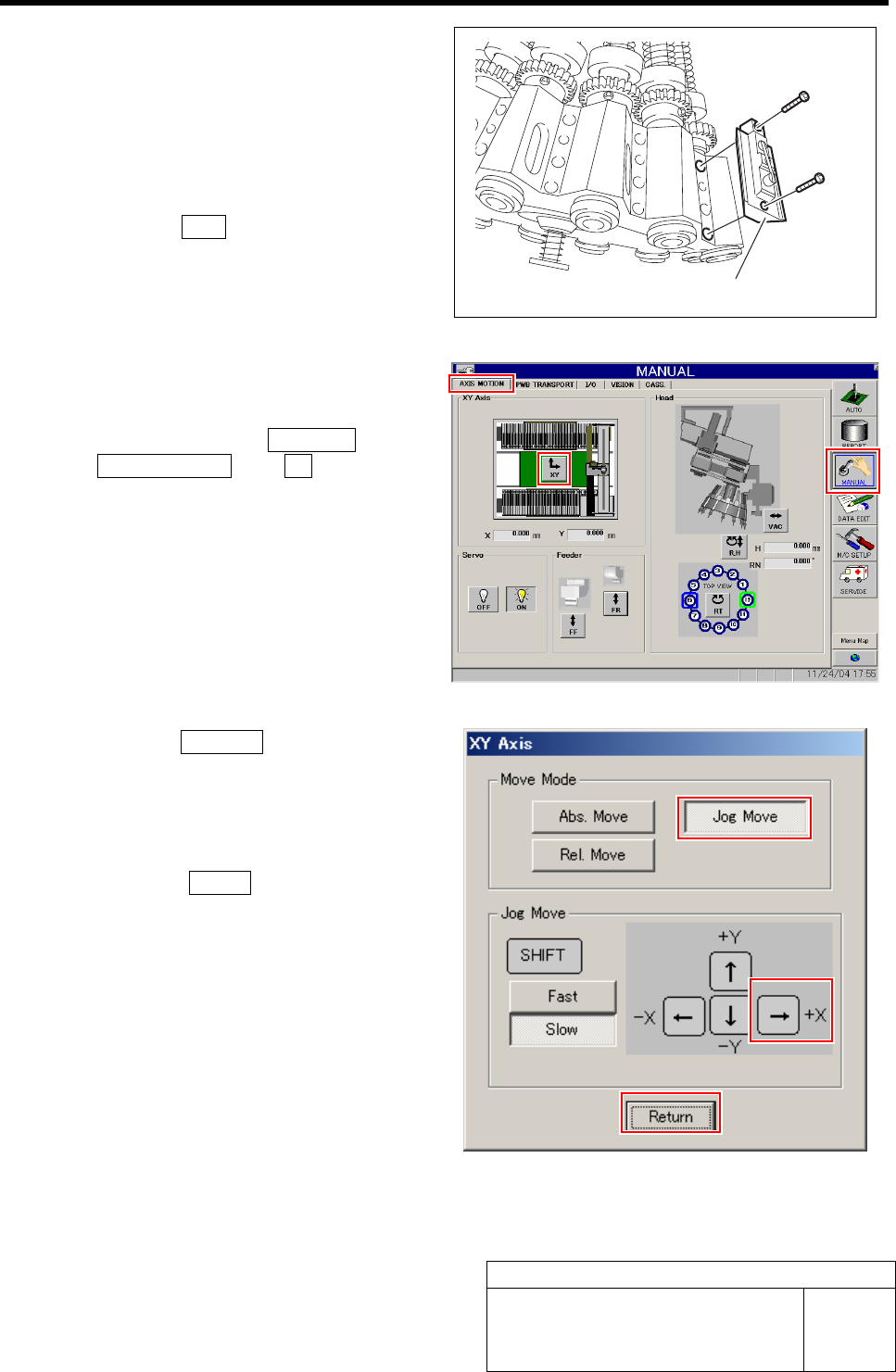
3 Perform origin position return of the unit.
1. Press the ORG button on the operation
panel with the HI screen being dis-
played.
4 Manually move the head unit to a position of
the center on the left and right of the X axis.
1. Click in an order of MANUAL menuÎ
AXIS MOTION tabÎXY button.
XY Axis screen is displayed.
2. Click the Jog Move button in the move
mode.
3. Press the right cursor key to jog move
the head unit to the center position on
the left and right.
4. Click the Return button to close the
XY Axis screen.
Mechanical valve