SI-F130 Manual(EN)_jpg_ Rev1.pdf - 第148页
Adjustment of PWB Sensor HLF-10419-01 Adjustment of PWB Sensor SHEET 1/1 Adjustment of PWB Sensor This section describes a proc edure to adjust sensitivity and installing position of PWB detec ting sensor (BS54, BS50). […
Phase Adjustment for Nozzle
HLF-10418-01
Phase Adjustment for Nozzle
SHEET
8/8
18 Adjust nozzle phases of No.2 to 12 in the same way as in the procedures 15 to 17, and then remove
the phase adjusting jig for nozzle and phase adjusting jig.
19 Fasten all screws on the right side of the
small gear.
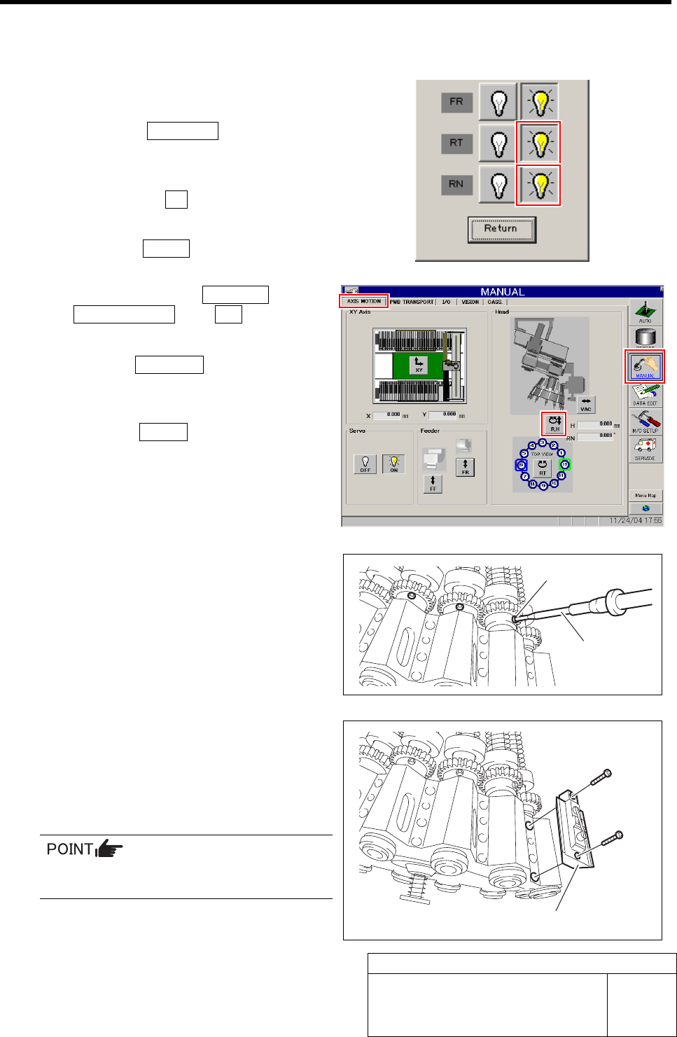
1. Click the Indv. Axis button on the
ORG OFFSET screen.
Indv. Axis servo screen is displayed.
2. Click the servo ON button for RT and RN.
Servo for RT, RN is turned off.
3. Click the Return button to close the
Indv. Axis servo screen.
4. Click in an order of MANUAL menuÎ
AXIS MOTION tabÎR.H button.
RN/H Axis screen is displayed.
5. Click the Abs. Move button.
6. Click the RN Axis button and input
“120” in angle input box.
7. Press the START button on the opera-
tion panel.
All of the inner shafts rotates by 120 degree and
right side screws of the small gear direct to out-
side.
8. Fasten all of the right side screws of
the small gear with a torque of
2kgf•m.
20 Install all mechanical valves.
1. Retighten the lower side cap screw
with a torque of 5kgf•m.
2. Retighten the upper side cap screw
with a torque of 5kgf•m.
When tightening the cap screw, retighten in
an order of upper side Î lower side screw.
21 Turn on the VACUUM breaker.
Torque driver
Right side screw
Mechanical valve
Adjustment of PWB Sensor
HLF-10419-01
Adjustment of PWB Sensor
SHEET
1/1
Adjustment of PWB Sensor
This section describes a procedure to adjust sensitivity and installing position of PWB detecting sensor (BS54,
BS50).
[Necessary jigs]
• Do not use jig.
[Procedure]
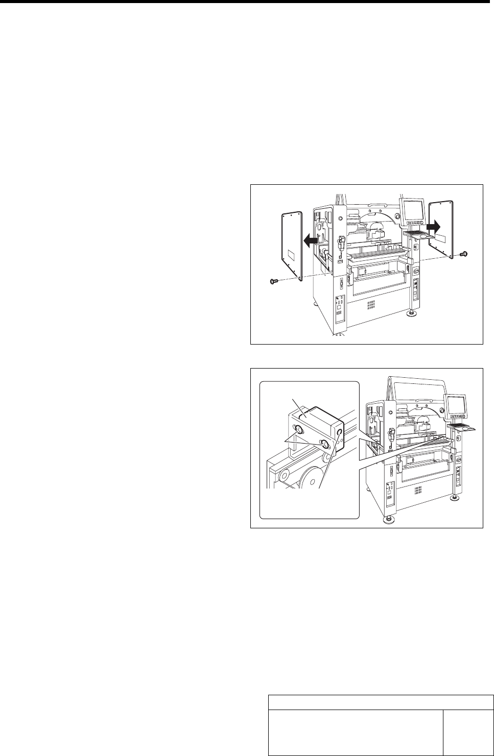
1 Remove the upper side panels on both sides
of the unit.
2 Adjust the sensitivity adjustment volume of
the PWB sensors (left side: BS54, right side:
BS50) installed on both ends of the con-
veyer to a position of 2/3.
3 Loosen the screw fastening the sensor, and
adjust the sensor position so that the screw
is at the center of the rectangular hole, and
then fasten the screw.
PWB sensor
Screw
Sensitivity
adjustment volume
Adjustment of Cassette Float Sensor Height
HLF-10420-01
Adjustment of Cassette Float Sensor
Height
SHEET
1/2
Adjustment of Cassette Float Sensor Height
This section describes a procedure to adjust the height of the cassette float sensor by using feed adjusting jig and
cassette float sensor height adjusting jig.
[Necessary jigs]
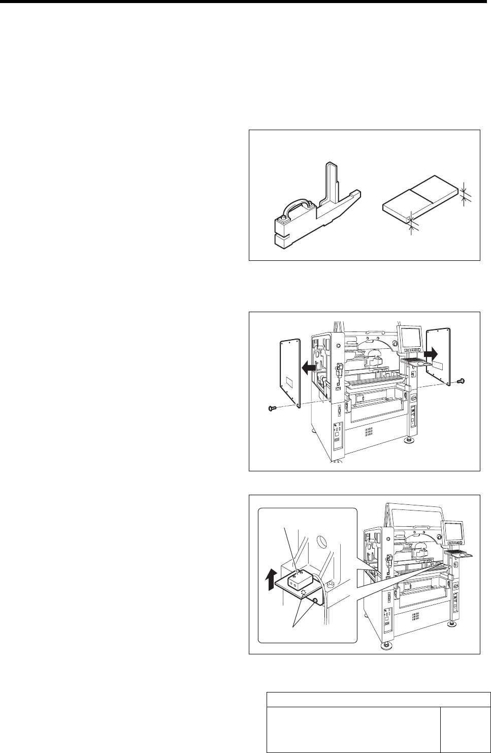
• Feed adjusting jig
• Cassette float sensor height adjusting jig
[Procedure]
1 Remove the upper side panels on both sides
of the unit.
2 Pull the bracket for the cassette float sensor
up to the upper end and temporarily tighten.
1. Loosen the cap screws (2-M4) on the
attachment bracket for the cassette
float sensors (left side: BS-63R, right
side: BS-63T) installed in the vertical
frame of the base stand.
2. Pull the bracket up to the upper end
and temporarily fasten.
3 Check that sensitivity level of BS-63R is
MAX.
Feed adjusting jig
Cassette float sensor
hei
g
ht ad
j
ustin
g
j
i
g
Cap screw
Cassette float sensor
6 mm
5 mm