SI-F130 Manual(EN)_jpg_ Rev1.pdf - 第152页
Adjustment of PWB S topper Sensor HLF-10421-01 Adjustment of PWB S topper Sensor SHEET 2/2 3 Adjust sensitivity of the PWB stopper senso r . 1. Set the gap between th e PWB and the PWB stopper to 2 mm. The gap can be eas…
Adjustment of PWB Stopper Sensor
HLF-10421-01
Adjustment of PWB Stopper
Sensor
SHEET
1/2
Adjustment of PWB Stopper Sensor
[Necessary jigs]
• Do not use jig.
[Procedure]
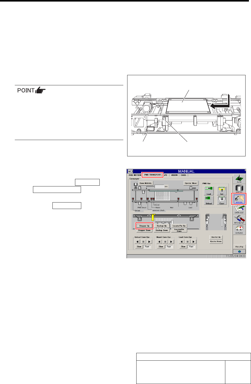
1 Set PWB on the conveyor.
Any PWB sized to be mountable on this
machine can be allowed.
Mountable PWB:
- Minimum PWB dimension: 50 x 50 mm
- Maximum PWB dimension: 460 x 360 mm
- PWB thickness: 0.5 to 2.6 mm
2 Raise the PWB stopper.
1. Click in an order of MANUAL menu
ÎPWB TRANSPORT tab to open the
PWB TRANSPORT screen.
2. Click the Stopper Up button to raise
the PWB stopper.
PWB
PWB stopper sensor
Sensor amplifier
Adjustment of PWB Stopper Sensor
HLF-10421-01
Adjustment of PWB Stopper
Sensor
SHEET
2/2
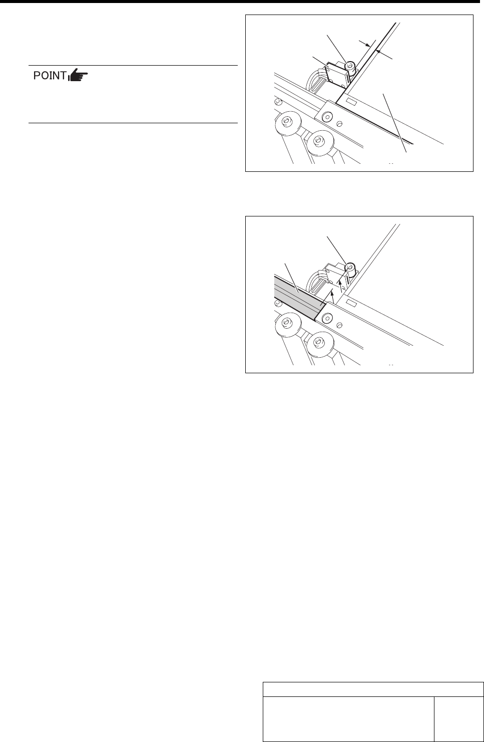
3 Adjust sensitivity of the PWB stopper sensor.
1. Set the gap between the PWB and the
PWB stopper to 2 mm.
The gap can be easily adjusted by inserting
a hexagon wrench of 2 mm between the
PWB and the PWB stopper.
2. Make adjustment by turning the sen-
sitivity adjustment volume of the sen-
sor amplifier so that the PWB stopper
sensor is turned on (both of the green
LED and orange LED light up) at this
position.
4 Check that the up end of the PWB stopper is
as high as the conveyor rail.
5 Remove the PWB.
PWB stopper sensor
2 mm
PWB
PWB stopper
Conveyor rail
PWB stopper
Fixed Camera Parts Presence/Absence Sensor Setup
HLF-10422-01
Fixed Camera Parts
Presence/Absence Sensor Setup
SHEET
1/4
Fixed Camera Parts Presence/Absence Sensor Setup
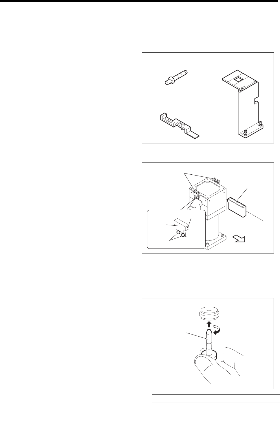
[Necessary jig]
• Nozzle jig for fixed camera
• Fixed camera parts presence/absence
sensor adjustment jig
• Fixed camera jig base
[Preparation before work]
1 Check that the displayed value on the parts
presence/absence sensor amplifier is “3800”
or more.
1. Check that the displayed value on the
parts presence/absence sensor ampli-
fier is “3800” or more.
When the displayed value is less than “3800”,
adjust the sensitivity according to the following
procedures 2. and 3.
2. Loosen the sensor bracket mounting
bolt, and move the sensor bracket up
and down, to left and right to adjust
the sensor mounting position.
3. Loosen the set screw to adjust the
sensor rotating direction.
2 Set the jig.
1. Install the Nozzle jig for fixed camera
to the turret No. 1.
Fixed camera jig base
Nozzle jig for fixed camera
Nozzle jig for fixed
camera
Fixed camera parts presence/
absence sensor
Front of unit
Set screw
Fixed camera parts presence/
absence sensor adjusting jig
Parts presence/
absence sensor
amplifier
Mounting bolt
Sensor
bracket