SI-F130 Manual(EN)_jpg_ Rev1.pdf - 第157页
Ejector Setup HLF-10423-01 Ejector Setup SHEET 1/3 Ejector Setup [Necessary jig] • Do not use jig. [Procedure] 1 Check that the sensor is not turne d on/off when the conveyor belt on the ORG se nsor and OT se nsor (CCW) …
Fixed Camera Parts Presence/Absence Sensor Setup
HLF-10422-01
Fixed Camera Parts
Presence/Absence Sensor Setup
SHEET
4/4
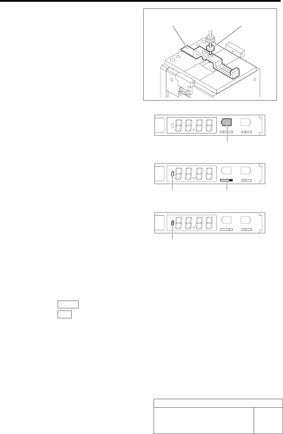
8 Next, move the head part so that the nozzle
jig can be inserted into the hole on the front
of the fixed camera parts presence/absence
sensor adjusting jig, and perform position-
ing.
9 Lower the nozzle jig by hand, and press the
TEACH button on the parts presence/
absence sensor amplifier for long time.
Check that the display state changes from green
lighting-up to number display.
TEACH
ADJ
SET RUN
LD
MODE
10 Turn the ADJ switch on the parts presence/
absence sensor amplifier to the “RUN” side.
Check that the ON/OFF display lamp on the parts
presence/absence sensor amplifier lights off.
TEACH
ADJ
SET RUN
LD
MODE
11 Again, insert the nozzle jig into the hole on
the back of the fixed camera parts pres-
ence/absence sensor adjusting jig, and
check that the ON/OFF display lamp on the
parts presence/absence sensor amplifier
lights up.
TEACH
ADJ
SET RUN
LD
MODE
12 Remove the jig.
1. Remove the nozzle jig and fixed camera parts presence/absence sensor adjusting jig.
2. Turn the emergency stop switch in the arrow direction to release the emergency stop state.
3. Press the RESET button on the operation panel to cancel the alarm.
4. Press the ORG button to perform origin position return.
5. Remove the fixed camera jig base and return the cover as previously.
Fixed camera parts presence/
absence sensor adjusting jig
Nozzle jig for
fixed camera
TEACH button
ADJ switch ON/OFF display lamp
ON/OFF display lamp
Ejector Setup
HLF-10423-01
Ejector Setup
SHEET
1/3
Ejector Setup
[Necessary jig]
• Do not use jig.
[Procedure]
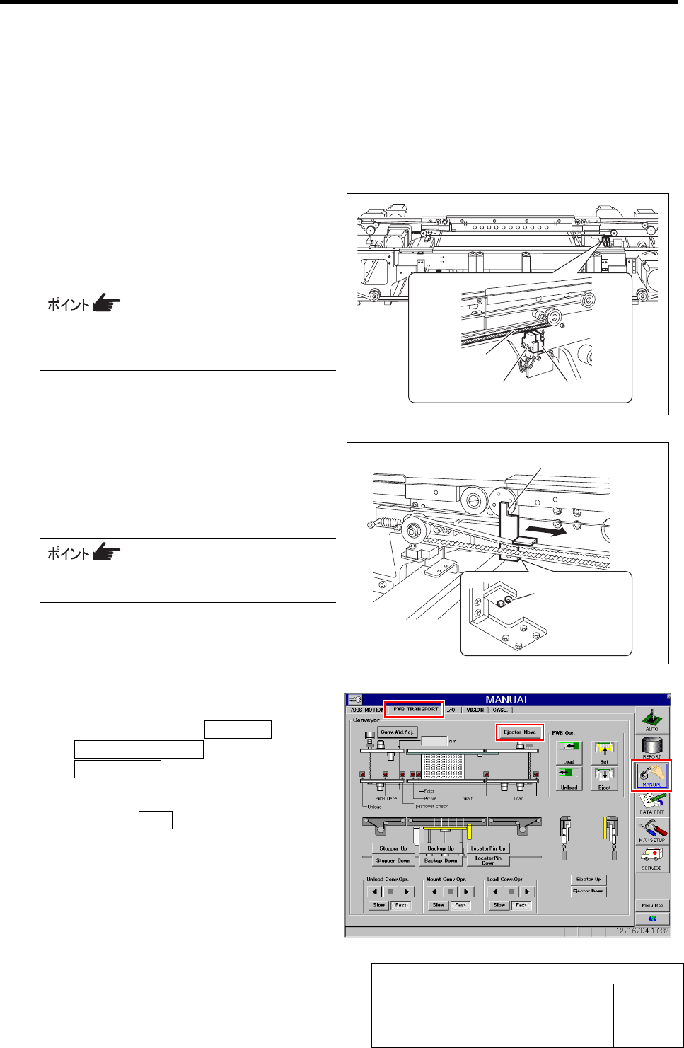
1 Check that the sensor is not turned on/off
when the conveyor belt on the ORG sensor
and OT sensor (CCW) is lowered or raised
by approximately 1 mm.
The sensor does not respond even if the
ejector belt oscillates with amplitude of 1
mm.
2 Loosen the mounting bolts (2) located on the
bottom face of the pusher, and shift the
pusher in right direction by hand to tempo-
rarily fasten.
Position of the mounting bolts can be con-
firmed by placing mirror below the pusher.
3 Return the ejector to the origin.
1. Click in an order of MANUAL menuÎ
PWB TRANSPORT tabÎ
Ejector Move button.
Ejector Move screen is displayed.
2. Press the ORG button on the operation
panel with the Ejector Move screen
being displayed.
The ejector returns to the origin.
Ejector belt
ORG sensor OT sensor
Mounting bolt
Pusher
Ejector Setup
HLF-10423-01
Ejector Setup
SHEET
2/3
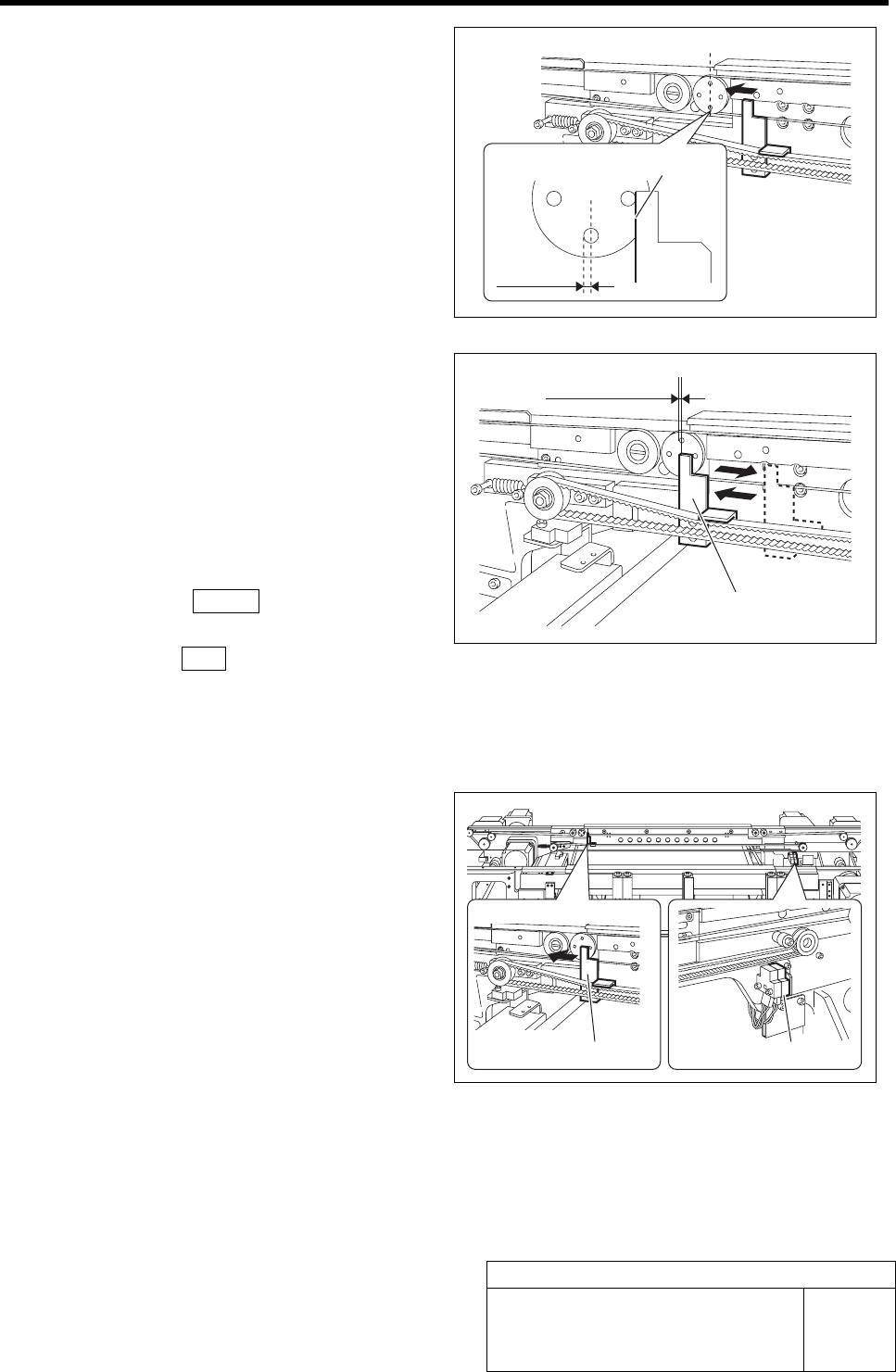
4 Adjust the pusher to the ORG position.
1. Loosen the pusher mounting bolts.
2. Move the pusher by hand so that the
pusher left face is at the ORG position.
3. Fasten the pusher mounting bolts to
fix the pusher.
5 After adjustment, check the ORG position.
1. Press the emergency stop switch to
turn off the servo.
2. Shift the pusher in right direction by
hand.
3. Turn the emergency stop switch in the
arrow direction to release the emer-
gency stop state.
4. Press the RESET button on the op-
eration panel.
5. Press the ORG button on the operation
panel with the Ejector Move screen
being displayed.
Check that the pusher returns to the position ad-
justed in the procedure 4.
6 Check the positions of the OT sensor (CCW)
and the mechanical stopper.
1. Press the emergency stop switch to
turn off the servo.
2. Move the pusher in left direction by
hand and check that the LED for the
OT sensor (CCW) lights up.
3. Further move the pusher in left direc-
tion and check that the pusher con-
tacts the mechanical stopper.
If the pusher contacts the mechanical stopper
prior to the OT sensor, adjust the sensor position
again.
Pusher left face
ORG
position
Pusher
ORG position
Pusher
OT sensor (CCW)