SI-F130 Manual(EN)_jpg_ Rev1.pdf - 第166页
Supplied Air Sensor Setup HLF-10426-01 Supplied Air Sensor Setup SHEET 1/2 Supplied Air Sensor Setup This section describes setting procedure for the Supplied Ai r sensor located on the on the interface panel on the back…
Blow Flow rate Setup
HLF-10425-01
Blow Flow rate Setup
SHEET
4/4
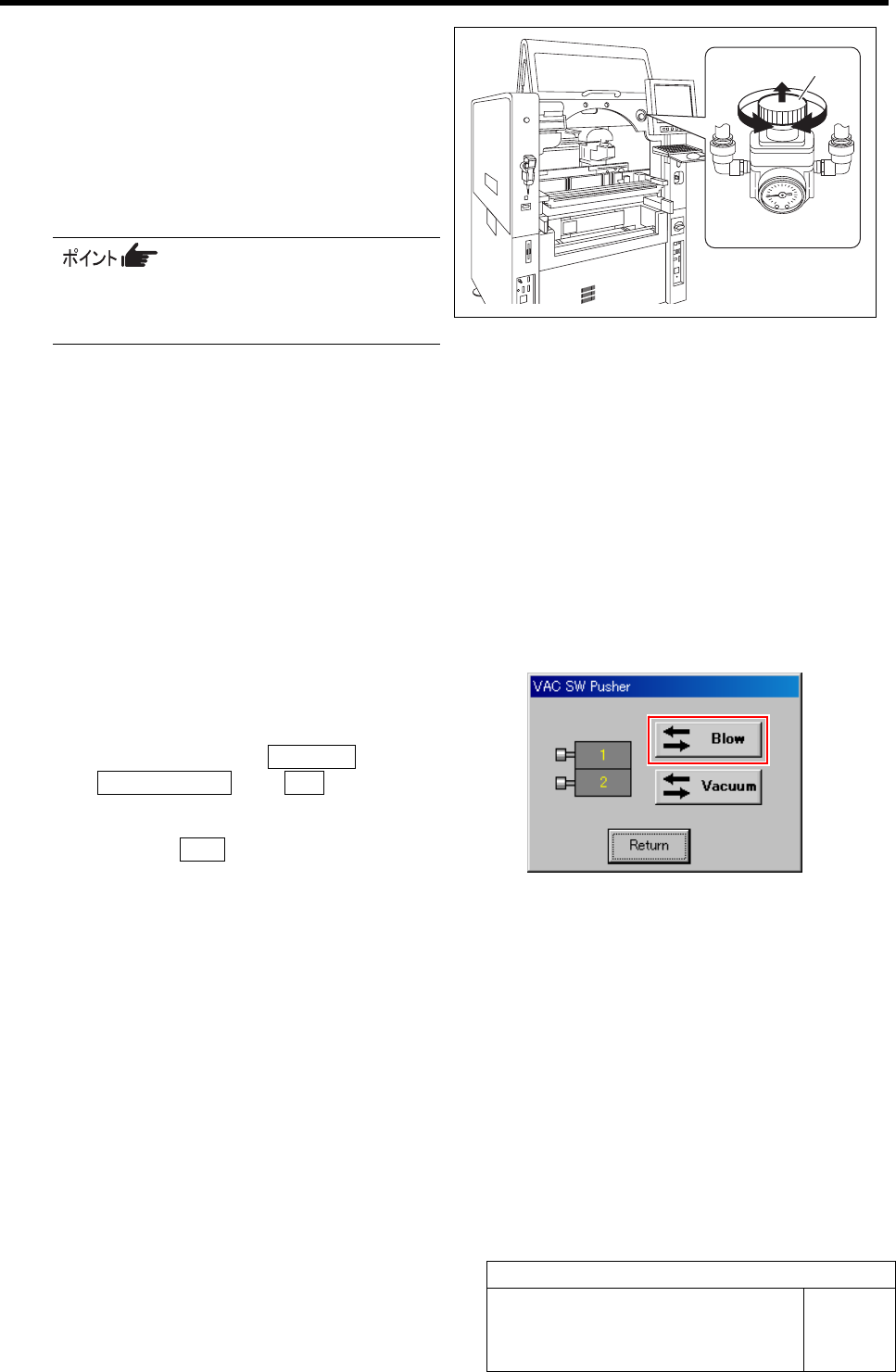
7 Turn the knob of the blow regulator to set the
measured value of the flowmeter to “0.28
L/min”.
1. Pull out the knob of the blow regulator
upward.
2. Turn the knob to adjust the air pres-
sure to “0.28 L/min”.
When adjusting the flow rate, make
measurement with the air tube being
straightened wherever possible.
3. Push in the knob downward and lock
the knob.
8 Check the blow flow rate of the turret No.2.
1. Remove the nozzle jig (AF12080) on the turret No.2.
2. Change the flow rate measuring nozzle jig on the turret No.1 onto the turret No.2.
3. Install the nozzle jig (AF12080) to the turret No.1.
4. Check that the measured value of the flowmeter is “0.20 L/min” or more.
5. Check that the value of the blow regulator is “0.015 to 0.035 MPa”.
9 Also check the blow flow rate of the turrets No.3 to 12 in the same procedure as in the procedure 8.
10 After adjusting blow flow rate, return the
blow back to OFF state.
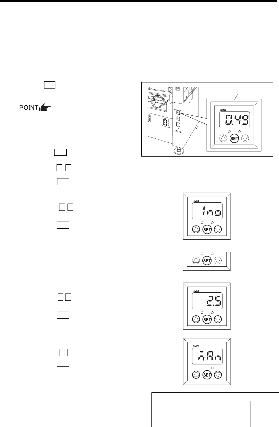
1. Click in an order of MANUAL menuÎ
AXIS MOTION tabÎVA C button.
VAC SW Pusher screen is displayed.
2. Click the Blow button.
The blow is turned off.
11 Remove the flow rate measuring nozzle jig
and nozzle jigs (11 pieces) mounted on the
turrets.
Knob
Blow regulator
Supplied Air Sensor Setup
HLF-10426-01
Supplied Air Sensor Setup
SHEET
1/2
Supplied Air Sensor Setup
This section describes setting procedure for the Supplied Air sensor located on the on the interface panel on the
back of the unit.
Set the Supplied Air sensor in an order of initial settingÎpressure setting.
[Initialize Procedure]
Set the output mode and response time.
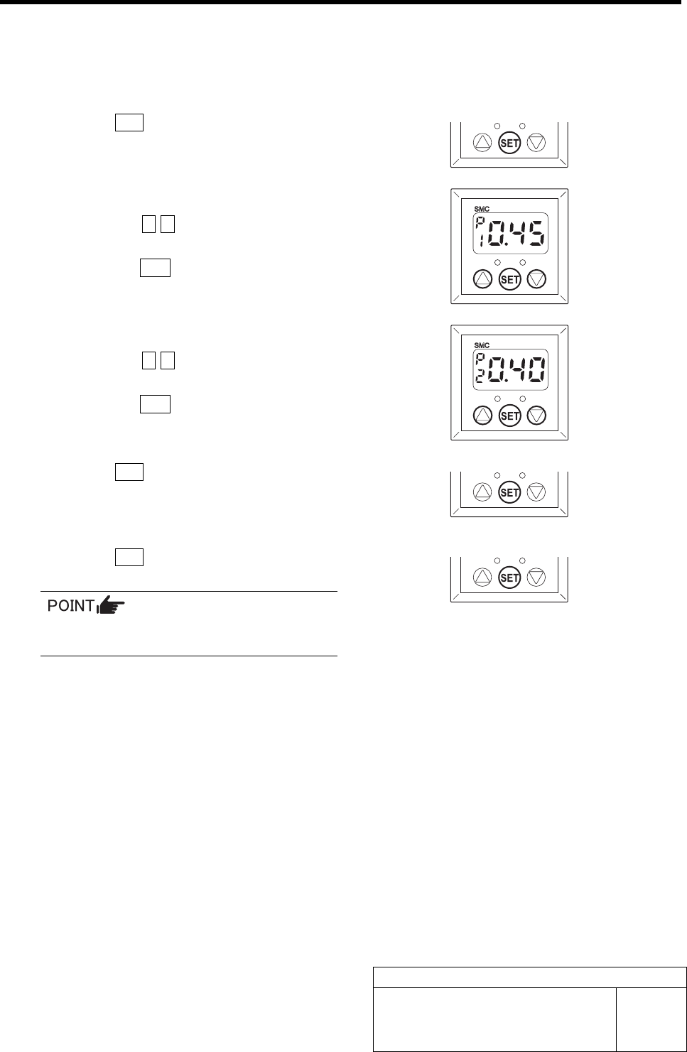
1 Press the SET button for longer than 2 seconds.
“Output mode (OUT1)” is displayed.
When operation is disabled even if each
button for the Supplied Air sensor is
pressed, key lock function is activated.
In this case, cancel the key lock function in
the following procedure.
1. Press the SET button for longer than 4
seconds.
2. Press the c d button to change the
indication from “LoC” to “UnL” and
press the SET button.
2 Set the output mode (OUT1).
1. Press the c d button to change the
indication to “1no”.
2. Press the SET button.
Output mode (OUT2) is displayed.
3 Because the output mode (OUT2) is not
used, press the SET button as it is.
Response time is displayed.
4 Set the response time.
1. Press the c d button to set the value
to “2.5” (msec).
2. Press the SET button.
Pressure setting is displayed.
5 Set the pressure.
1. Press the c d button to change the
indication to “nAn”.
2. Press the SET button.
Return to the Measurement mode.
Supplied Air sensor
Supplied Air Sensor Setup
HLF-10426-01
Supplied Air Sensor Setup
SHEET
2/2
[Pressure setting Procedure]
Set the set value for each mode selected by the initial setting.
1 Press the SET button.
“P_1” and the set value are alternately displayed.
2 Set the set value for the output mode (P1).
1. Press the c d button to set the value
to “0.45”.
2. Press the SET button.
“P_2” and the set value are alternately displayed.
3 Set the set value for the output mode (P2).
1. Press the c d button to set the value
to “0.40”.
2. Press the SET button.
“P_3” and the set value are alternately displayed.
4 Press the SET button.
“P_4” and the set value are alternately displayed.
5 Press the SET button.
Return to the Measurement mode.
Because the output modes (P3) and (P4)
are not used, do not set the values.