SI-F130 Manual(EN)_jpg_ Rev1.pdf - 第169页
V acuum Sensor Setup HLF-10427-01 V acuum Sensor Setup SHEET 2/2 [Pressure setting Procedure] Set the set value for each mode se lected by the initial setting. 1 Press the SET button. “P_1” and the set value ar e alterna…
Vacuum Sensor Setup
HLF-10427-01
Vacuum Sensor Setup
SHEET
1/2
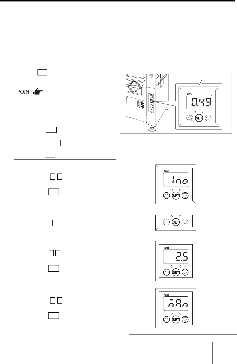
Vacuum Sensor Setup
This section describes setting procedure for the Vacuum sensor located on the on the interface panel on the back of
the unit.
Set the Vacuum sensor in an order of initial settingÎpressure setting.
[Initialize Procedure]
Set the output mode and response time.
1 Press the SET button for longer than 2 seconds.
“Output mode (OUT1)” is displayed.
When operation is disabled even if each
button for the Vacuum sensor is pressed,
key lock function is activated.
In this case, cancel the key lock function in
the following procedure.
1. Press the SET button for longer than 4
seconds.
2. Press the c d button to change the
indication from “LoC” to “UnL” and
press the SET button.
2 Set the output mode (OUT1).
1. Press the c d button to change the
indication to “1no”.
2. Press the SET button.
Output mode (OUT2) is displayed.
3 Because the output mode (OUT2) is not
used, press the SET button as it is.
Response time is displayed.
4 Set the response time.
1. Press the c d button to set the value
to “2.5” (msec).
2. Press the SET button.
Pressure setting is displayed.
5 Set the pressure.
1. Press the c d button to change the
indication to “nAn”.
2. Press the SET button.
Return to the Measurement mode.
Vacuum sensor
Vacuum Sensor Setup
HLF-10427-01
Vacuum Sensor Setup
SHEET
2/2
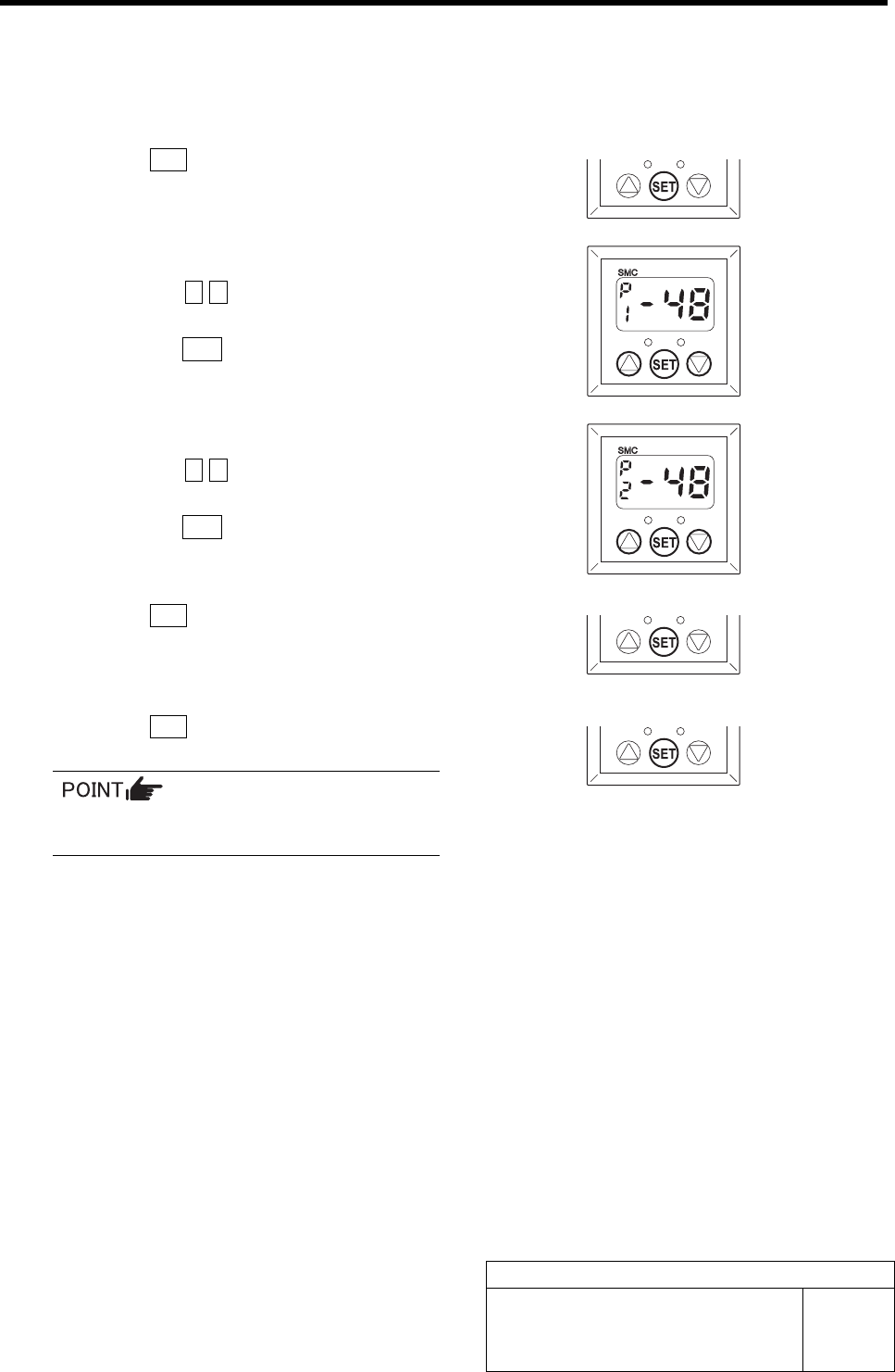
[Pressure setting Procedure]
Set the set value for each mode selected by the initial setting.
1 Press the SET button.
“P_1” and the set value are alternately displayed.
2 Set the set value for the output mode (P1).
1. Press the c d button to set the value
to “-48”.
2. Press the SET button.
“P_2” and the set value are alternately displayed.
3 Set the set value for the output mode (P2).
1. Press the c d button to set the value
to “-48”.
2. Press the SET button.
“P_3” and the set value are alternately displayed.
4 Press the SET button.
“P_4” and the set value are alternately displayed.
5 Press the SET button.
Return to the Measurement mode.
Because the output modes (P3) and (P4)
are not used, do not set the values.
3 Mechanical Layout