SI-F130 Manual(EN)_jpg_ Rev1.pdf - 第21页
RT Axis Origin Position Set up HLF-10201-01 RT A xis Origin Position Setup SHEET 4/5 3. Click the RT Axis Home button on the Machine Setup screen. R T Axis Home screen is d isplayed. 7 Click the servo OFF button to turn …
RT Axis Origin Position Setup
HLF-10201-01
RT Axis Origin Position Setup
SHEET
3/5
4 Move the head unit onto the calibration plate
jig by manual operation.
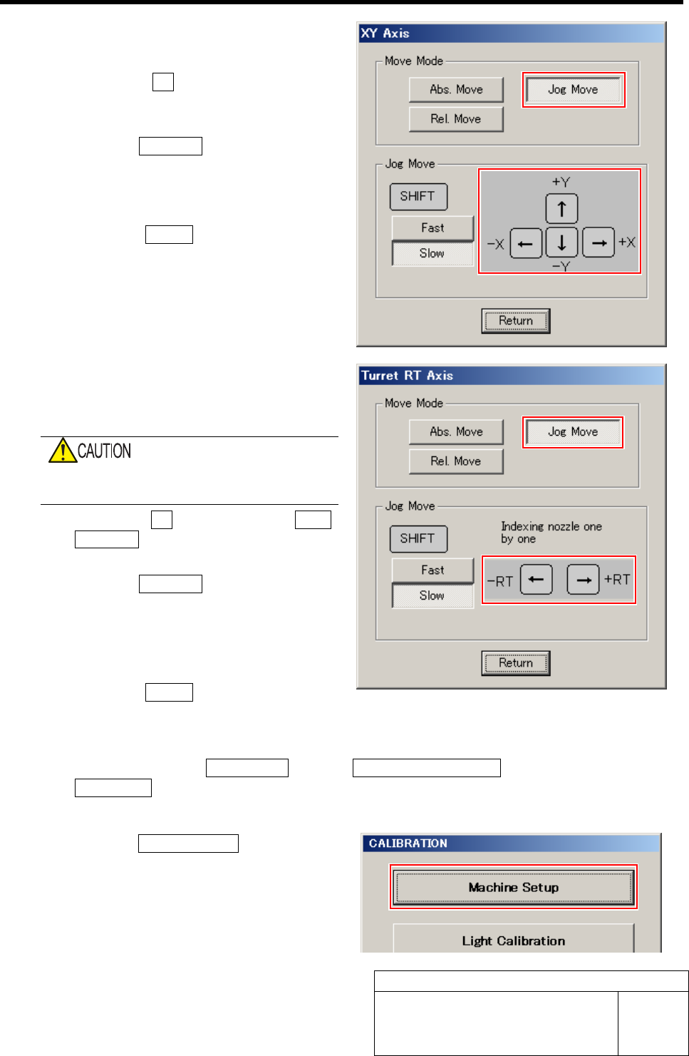
1. Press the XY button for the AXIS
MOTION screen.
XY Axis screen is displayed.
2. Click the Jog Move button in the move
mode.
3. Press the cursor key to jog move the
head unit onto the calibration plate jig.
4. Click the Return button to close the
XY Axis screen.
5 Move the jig shaft placed into the turret No.1
to the placement position by jog moving the
RT axis.
Be careful so that the RT jig shaft does not
collide the camera plate.
1. Click the RT button on the AXIS
MOTION screen.
Turret RT Axis screen is displayed.
2. Click the Jog Move button in the move
mode.
3. Press the left and right cursor keys to
move the jig shaft to the placement
position.
4. Click the Return button to close the
Turret RT Axis screen.
6 Display RT Axis Home screen.
1. Click in an order of M/C SETUP menu Î M/C MAINTENANCE tabÎ
Calibration button.
CALIBRATION screen is displayed.
2. Click the Machine Setup button on the
CALIBRATION screen.
Machine Setup screen is displayed.
RT Axis Origin Position Setup
HLF-10201-01
RT Axis Origin Position Setup
SHEET
4/5
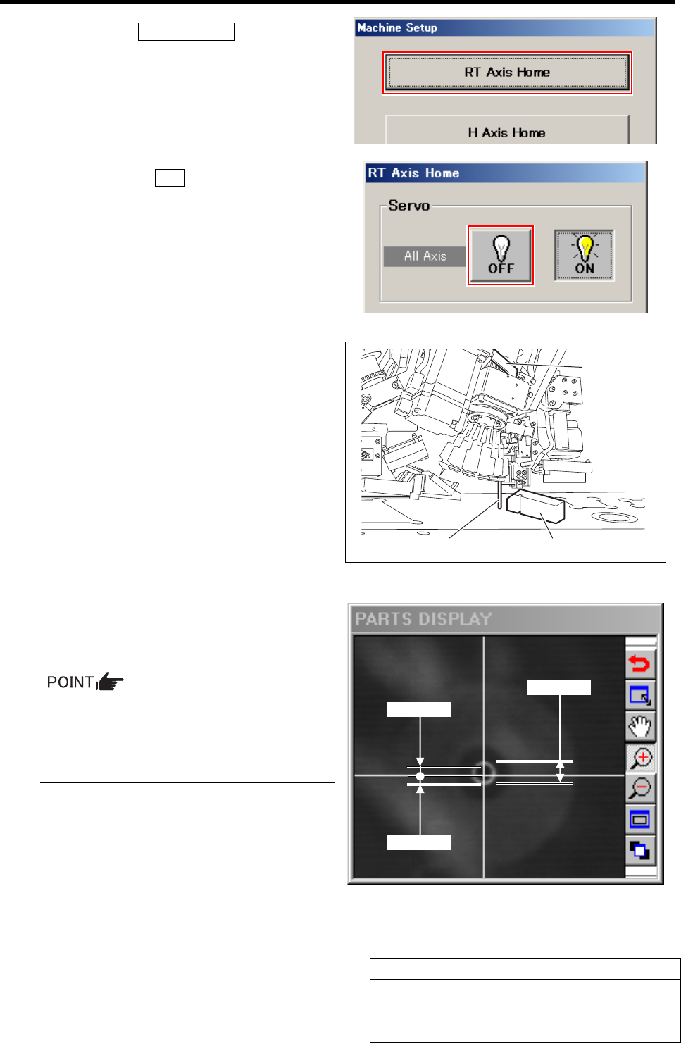
3. Click the RT Axis Home button on the
Machine Setup screen.
RT Axis Home screen is displayed.
7 Click the servo OFF button to turn off the
servos for all axes.
8 Adjust by turning the RT axis so that the RT
jig shaft can be smoothly inserted into the
groove of the RT jig block.
1. Place the RT jig block onto the cali-
bration plate jig.
2. Adjust the axis position by turning the
RT axis belt by hand so that the RT jig
shaft can be smoothly inserted into the
groove of the RT jig block.
9 Check that a cross hairs are within the out-
side diameter of the nozzle jig (AF06040) on
PARTS DISPLAY (Tolerance: ±0.3 mm)
It is advisable to roughly adjust the nozzle
center by turning the RT axis by hand
while seeing PARTS DISPLAY and then
the RT jig shaft can easily mate the RT jig
block groove.
0.3 mm
0.3 mm
Φ0.6 mm
RT jig shaft
RT jig block
RT axis belt
RT Axis Origin Position Setup
HLF-10201-01
RT Axis Origin Position Setup
SHEET
5/5
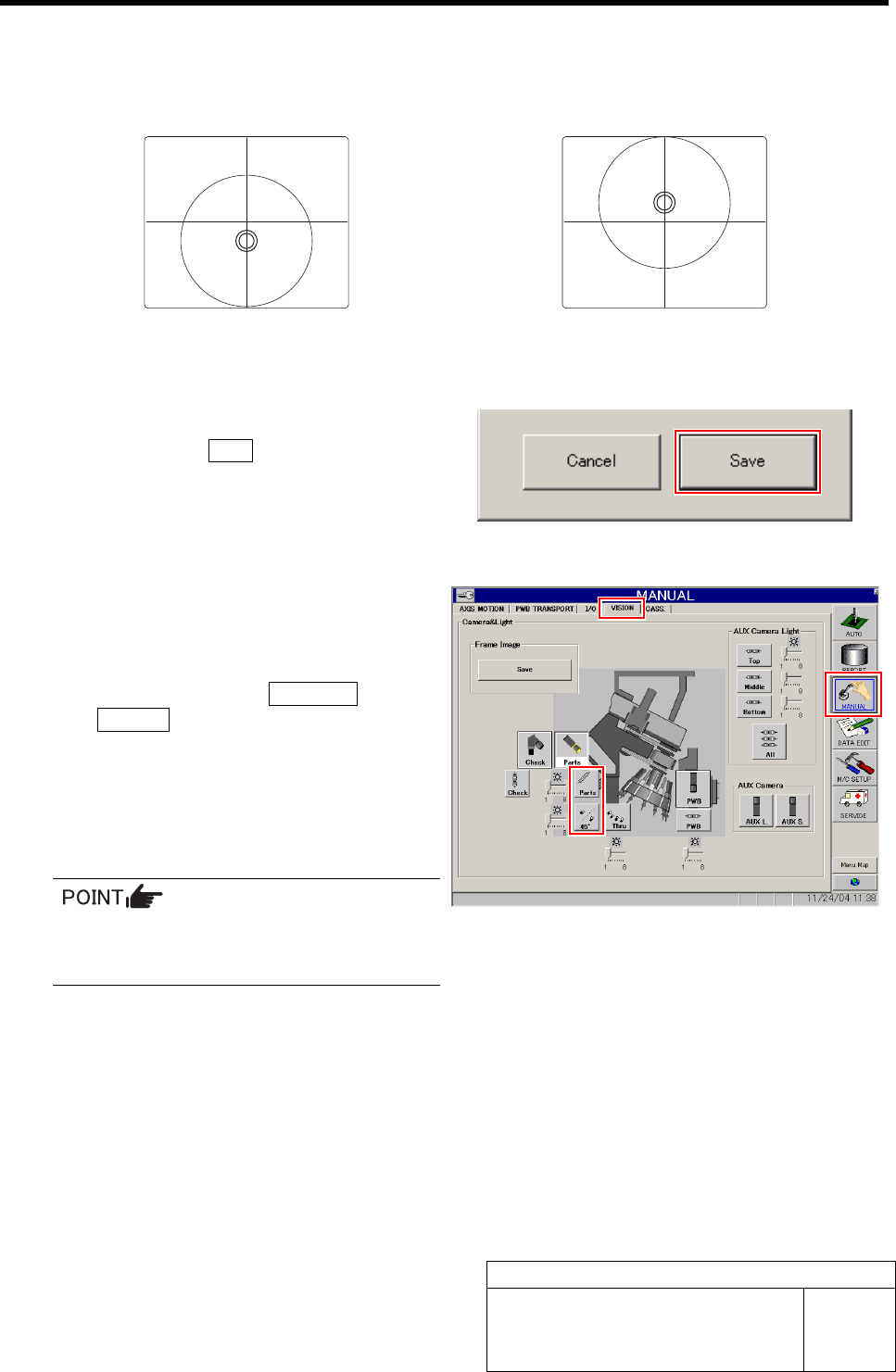
If the discrepancy of the nozzle jig (AF06040) is excessive in the PARTS DISPLAY, check
whether the pin can enter the camera bracket.
If the pin enters for camera bracket but the cross hairs fail to enter the outside diameter of the
nozzle, adjust with a spacer as shown in figures below.
If the nozzle deviates below the cross hairs,
insert a spacer.
If the nozzle deviates above the cross hairs, re-
move a spacer.
10 When position of the RT jig shaft is deter-
mined, click the Save button while holding
the RT axis by hand so that it does not
move.
The present position is saved and the RT Axis Home
screen closes.
11 Check that the cross hairs enter the outside
diameter of the nozzle jig (AF06040) in the
PARTS DISPLAY of the VISION screen.
1. Click in an order of MANUAL menuÎ
VISION tab.
2. Click the LED button for parts camera
to light the LED.
3. Check that the cross hairs are within
the outside diameter of the nozzle jig
(AF06040).
If image on PARTS DISPLAY can be
hardly seen, adjust brightness with
brightness slider of the LED.
12 Remove the jig and install spring, steel balls and O-ring to the inner shaft.