SI-F130 Manual(EN)_jpg_ Rev1.pdf - 第60页
Parts Camera Calibration HLF-10309-01 Parts Camera Calibration SHEET 2/3 5 Install the nozzl e jig (AF80400) to the turrets No. 1 to 4 and press the ST ART button on the operation panel. The turrets rotat e and the turre…
Parts Camera Calibration
HLF-10309-01
Parts Camera Calibration
SHEET
1/3
Parts Camera Calibration
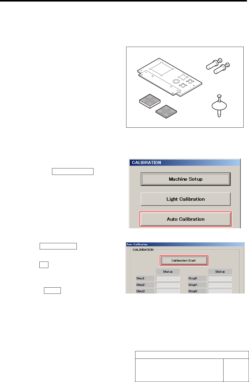
[Necessary jigs]
• Calibration plate jig
• Jig positioning pin
• Nozzle jig (AF80400)
• Jig chip (t=3.4 mm, t=1.4 mm)
[Procedure]
1 Display a Auto Calibration screen.
1. Click the Auto Calibration button on
the CALIBRATION screen.
Auto Calibration screen is displayed.
2 Click the Calibration Start button.
“Setup jig?” is displayed on the message screen.
3 Click the Yes button.
“Press [START] to move to nozzle installing position”
is displayed on the message screen.
4 Press the START button on the operation
panel.
Turrets No.1 to 4 move to the jig setup position.
Jig positioning pin
Calibration plate jig
Jig chip
(t=3.4 mm, t=1.4 mm)
Nozzle jig (AF80400)
Parts Camera Calibration
HLF-10309-01
Parts Camera Calibration
SHEET
2/3
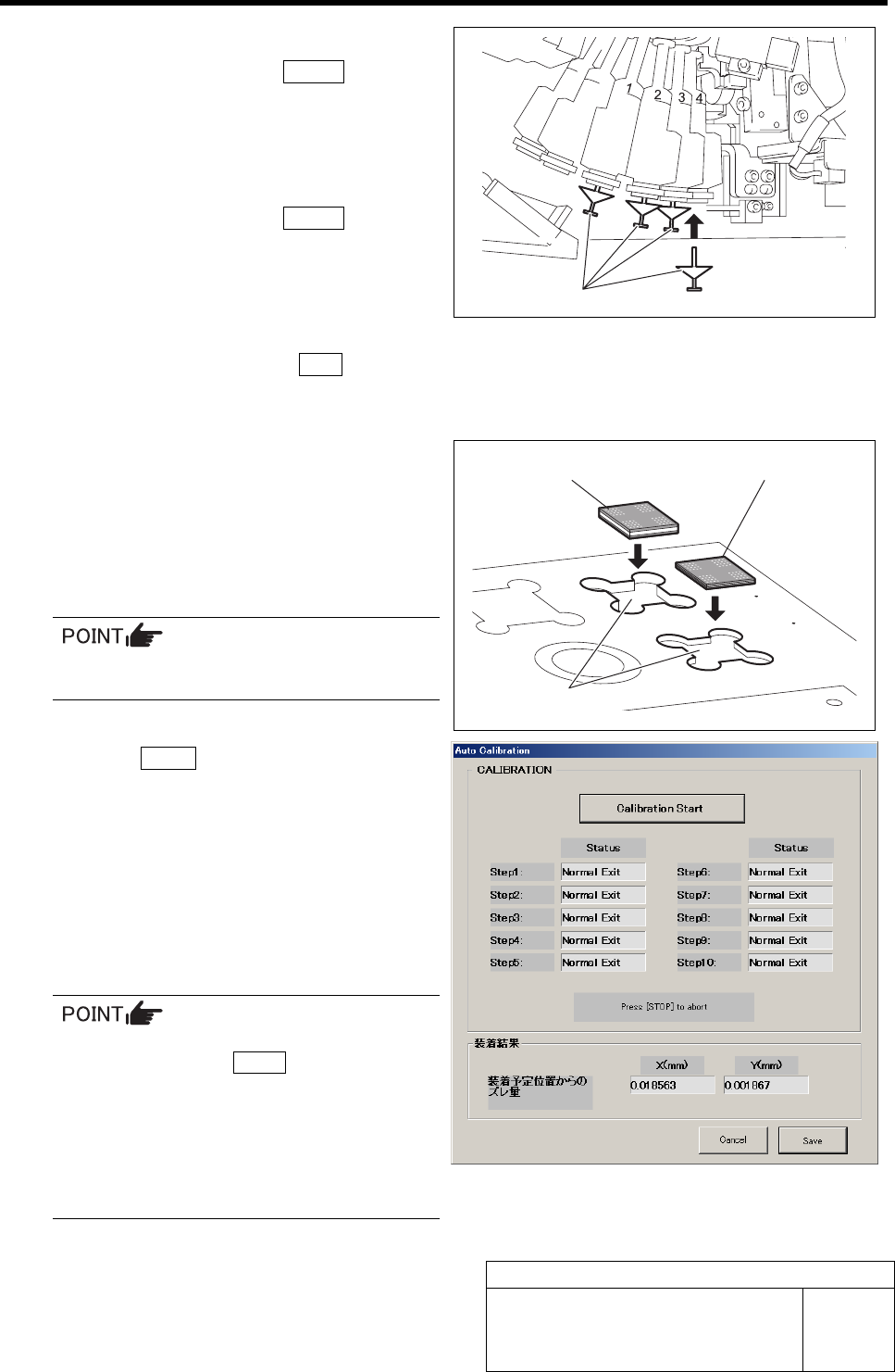
5 Install the nozzle jig (AF80400) to the turrets
No. 1 to 4 and press the START button on
the operation panel.
The turrets rotate and the turrets No.5 to 8 move to the
jig setup position.
6 Install the nozzle jig (AF80400) to the turrets
No. 5 to 8 and press the START button on
the operation panel.
The turrets rotate and the turrets No.9 to 12 move to
the jig setup position.
7 Install the nozzle jig (AF80400) to the turrets
No. 9 to 12 and press the ORG button on
the operation panel.
Origin position return of the unit is performed.
8 Set the jig chips to the tip insertion part on
the calibration plate jig.
1. Insert the jig chip (t=3.4 mm) into the
tip insertion part on the farther side.
2. Insert the jig chip (t=1.4 mm) into the
tip insertion part on the near side.
Set the jig chip as to be near on the right.
9 Press the START button on the operation panel.
Auto calibration is started.
If any error occurs in Step 1, re-perform unit reference
position setting.
If any error occurs in Step 2 to 10, perform the fol-
lowings and re-perform Auto calibration.
- Re-perform light calibration.
- Clean the jig chip with alcohol.
- Clean the mirror of the parts camera portion with alcohol.
•When stopping in course of Auto calibra-
tion, press the STOP button to stop
when the nozzle does not pick up the jig
chip, or after checking that the jig chip is
placed on the calibration plate jig.
•When stopping in course of Auto calibra-
tion, the calibration can not be re-started
from the halfway the step.
Auto calibration ends after approximately one hour.
Nozzle jig (AF80400)
Jig chip (t=1.4 mm)
Jig chip (t=3.4 mm)
Tip insertion part
Parts Camera Calibration
HLF-10309-01
Parts Camera Calibration
SHEET
3/3
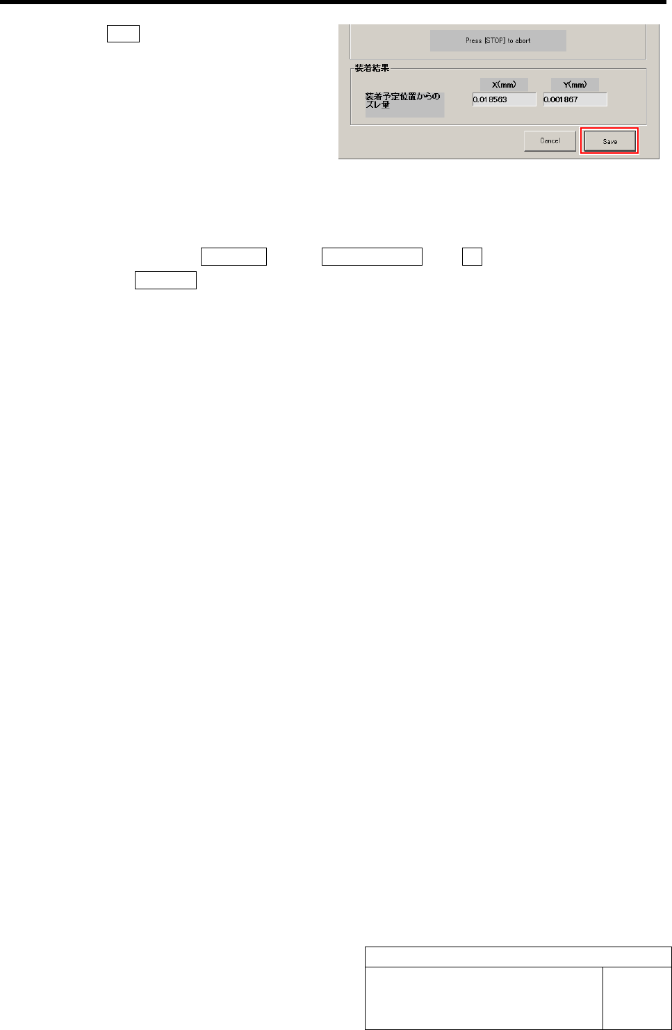
10 Click the Save button.
Information of the Auto calibration is saved and the
Auto calibration screen closes.
11 Remove the nozzle jig (AF80400) and jig chip.
1. Close the calibration screen.
2. Click in an order of MANUAL menuÎAXIS MOTION tabÎRT button.
3. Click the Jog Move button.
4. Press the left and right cursor keys to rotate the turrets, and remove all of the nozzle jig
(AF80400).
5. Remove the jig chips on the calibration plate jig.