SI-F130 Manual(EN)_jpg_ Rev1.pdf - 第75页
Fixed Camera Cali bration HLF-10313-01 Fixed Camera Calibration SHEET 4/7 8 Adjust the center of the nozzl e jig picking up the fixed camera jig 1 to cross hairs on the P ARTS DISPLA Y . 1. Jog move the XY axis to a posi…
Fixed Camera Calibration
HLF-10313-01
Fixed Camera Calibration
SHEET
3/7
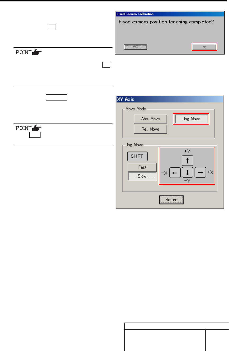
7 Jog move the fixed camera jig 1 picked up
by the nozzle jig onto the fixed camera.
1. Press the No button on the message
screen.
XY Axis screen is displayed.
When re-performing the fixed camera cali-
bration due to error etc., click the Yes
button.
The head portion automatically moves
onto the fixed camera.
2. Click the Jog Move button.
3. Press the cursor key to jog move the
fixed camera jig 1 picked up by the
nozzle jig onto the fixed camera.
If the Shift key on the keyboard is pressed,
Fast/Slow for Jog Move can be switched.
Fixed Camera Calibration
HLF-10313-01
Fixed Camera Calibration
SHEET
4/7
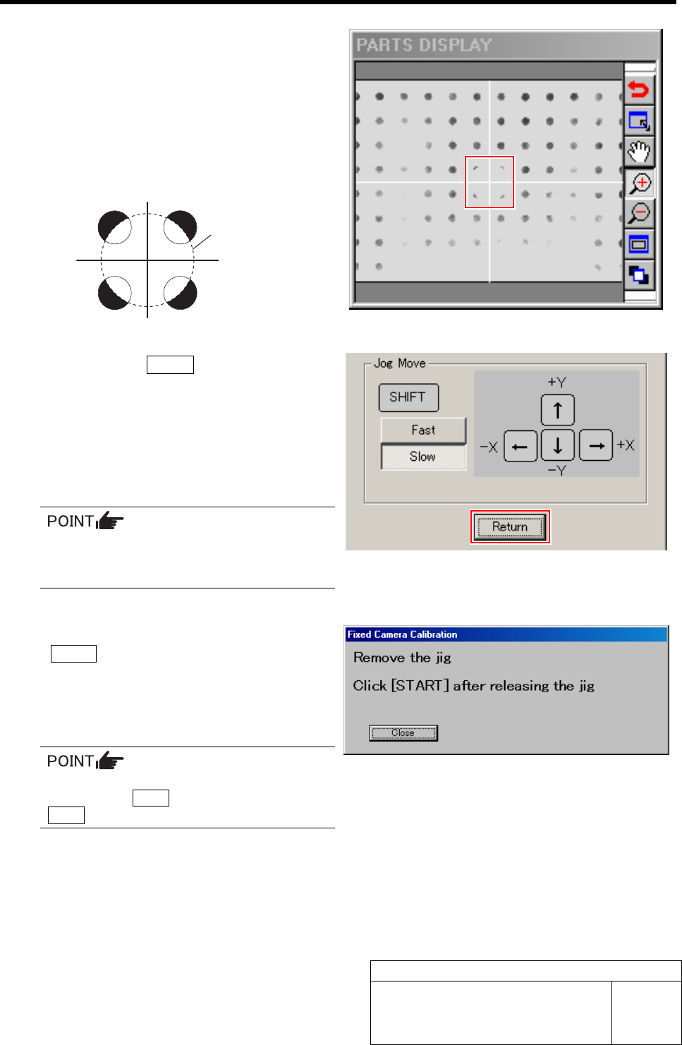
8 Adjust the center of the nozzle jig picking up
the fixed camera jig 1 to cross hairs on the
PARTS DISPLAY.
1. Jog move the XY axis to a position
where the cross hairs on the PARTS
DISPLAY and outline of the nozzle jig
are equally seen from the fixed camera
jig holes as in the figure below.
2. Click the Return button on the XY
Axis screen.
The fixed camera jig 1 automatically lowers to
the Rcg height and recognition for calculation of
pixel rate.
If recognition normally ends, the head automati-
cally moves to the nozzle replacing position.
If any error occurs, remove the fixed cam-
era jig 1 to return it to the previous posi-
tion and re-perform from the procedure 2.
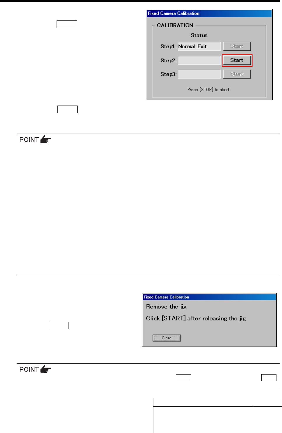
9 Remove the fixed camera jig 1 and press the
START button on the operation panel.
The screen returns to the Fixed Camera Calibration
screen, and “Normal Exit” is displayed in the box for
Step 1.
Since the content up to then is cancelled if
pressing the Close button, do not press the
Close button except for interruption.
Outline of nozzle jig
(AF80400)
Fixed Camera Calibration
HLF-10313-01
Fixed Camera Calibration
SHEET
5/7
10 Start the Step 2.
1. Click the START button for Step 2.
“Press [START] to recognize relationship be-
tween PWB camera and Fixed camera” is dis-
played on the message screen.
2. Press the START button on the operation panel.
After PWB camera automatically recognized 4 holes on the right front of the fixed camera jig 2, it picks up the fixed
camera jig 2 and recognizes above the fixed camera.
• If any error occurs, remove the fixed camera jig 2 to return it to the previous position on the
calibration plate jig and re-perform from the procedure 10.
• If the error occurs repeatedly, perform the followings.
1). Slightly change the position of the fixed camera jig 2 on the calibration plate jig.
2). Close all of the calibration screens, open the file of “C: ¥asm¥mcdata¥calib.ini” from ex-
plorer with wordpad, change the next lighting condition and then re-perform from the first
procedure.
LIGHT_PWB_BGA:
Lighting condition for 4 holes of the right front of the fixed camera jig 2 recognized by PWB
camera in the Step 2, 3. Lighting condition can be set in 8 stages of 1 to 8.
LIGHT_FIXED_BGA:
Lighting condition for the fixed camera jig 2 recognized by fixed camera in the Step 2, 3.
The third left digit from decimal point of the three digits number represents brightness of
coaxial upper stage, the second digit represents that of coaxial middle stage and the first
digit represents that of coaxial lower stage, and the lighting condition can be respectively
set in 8 stages of 1 to 8.
If normally ended, “Remove the jig. Click [START] after releasing the jig” is displayed on the message screen.
11 Remove the fixed camera jig 2 picked up by
the nozzle jig (AF80400), and return it to the
previous position on the calibration plate jig.
12 Press the START button on the operation
panel.
The screen returns to the Fixed Camera Calibration
screen, and “Normal Exit” is displayed in the box for
Step 2.
Since the content up to then is cancelled if pressing the Close button, do not press the Close
button except for interruption.