SI-F130 Manual(EN)_jpg_ Rev1.pdf - 第80页
Pickup Position Setup HLF-10314-01 Pickup Position Setup SHEET 2/7 2 Press the ORG button on the operation p anel to perform origin position return. 3 Open the Cassette Pos. Dat a. 1. Click in an order of M/C SETUP menu …
Pickup Position Setup
HLF-10314-01
Pickup Position Setup
SHEET
1/7
Pickup Position Setup
Pickup position setup can be performed at three locations on the front cassette table (Z106, Z120,
Z139) and at three locations on the rear cassette table (Z202, Z220, Z235).
Acquire XY position and H position by using jig at the respective position to setup pickup position.
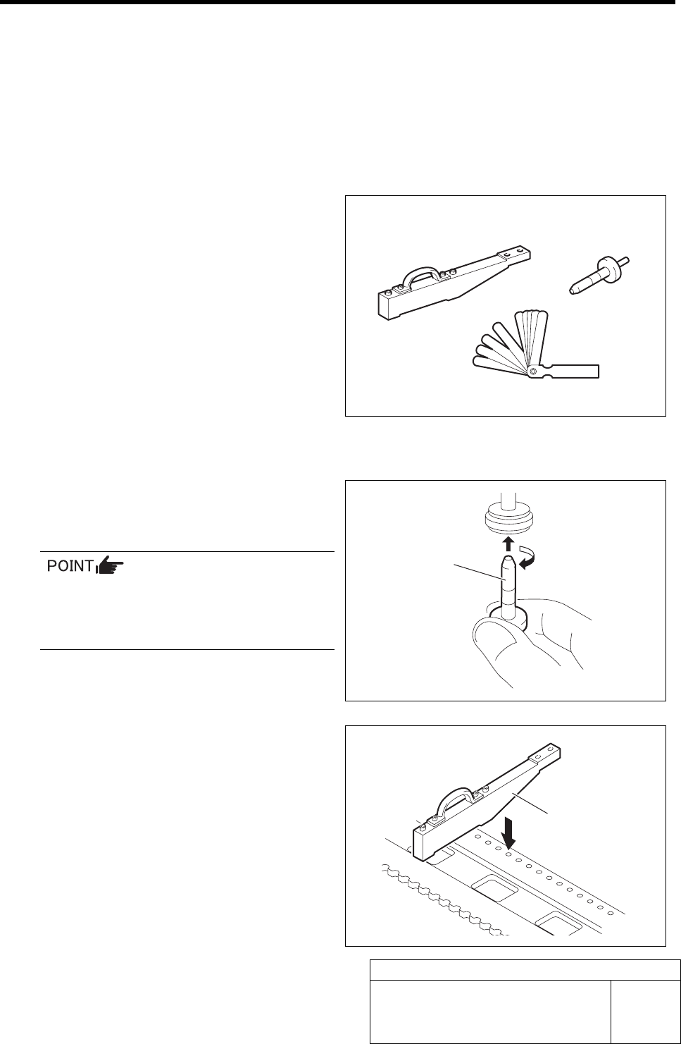
[Necessary jigs]
• Pickup point jig
• Length reference nozzle jig
• Thickness gauge (t=0.03 mm)
[Procedure]
1 Set the jig.
1. Install the length reference nozzle jig
to the turret No.1.
When installing the nozzle, insert it while
slowly turning.
After inserting the nozzle, check that it is
not drawn out by pulling downward.
2. Set pickup point jig to Z106 on the
cassette table.
Pickup point jig
Length reference
nozzle jig
Thickness gauge
Pickup point jig
Length reference
nozzle jig
Pickup Position Setup
HLF-10314-01
Pickup Position Setup
SHEET
2/7
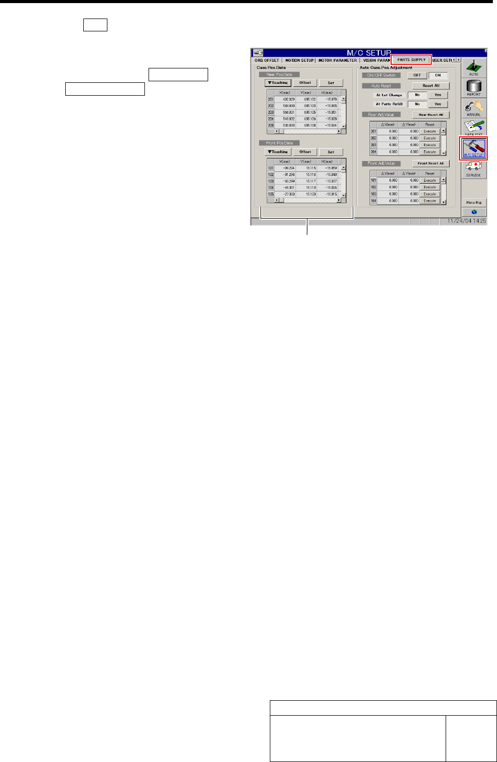
2 Press the ORG button on the operation panel to perform origin position return.
3 Open the Cassette Pos. Data.
1. Click in an order of M/C SETUP menu
ÎPARTS SUPPLY tab.
Cassette position coordinates are displayed on
left part of the PARTS SUPPLY screen.
Cassette position coordinates
Pickup Position Setup
HLF-10314-01
Pickup Position Setup
SHEET
3/7
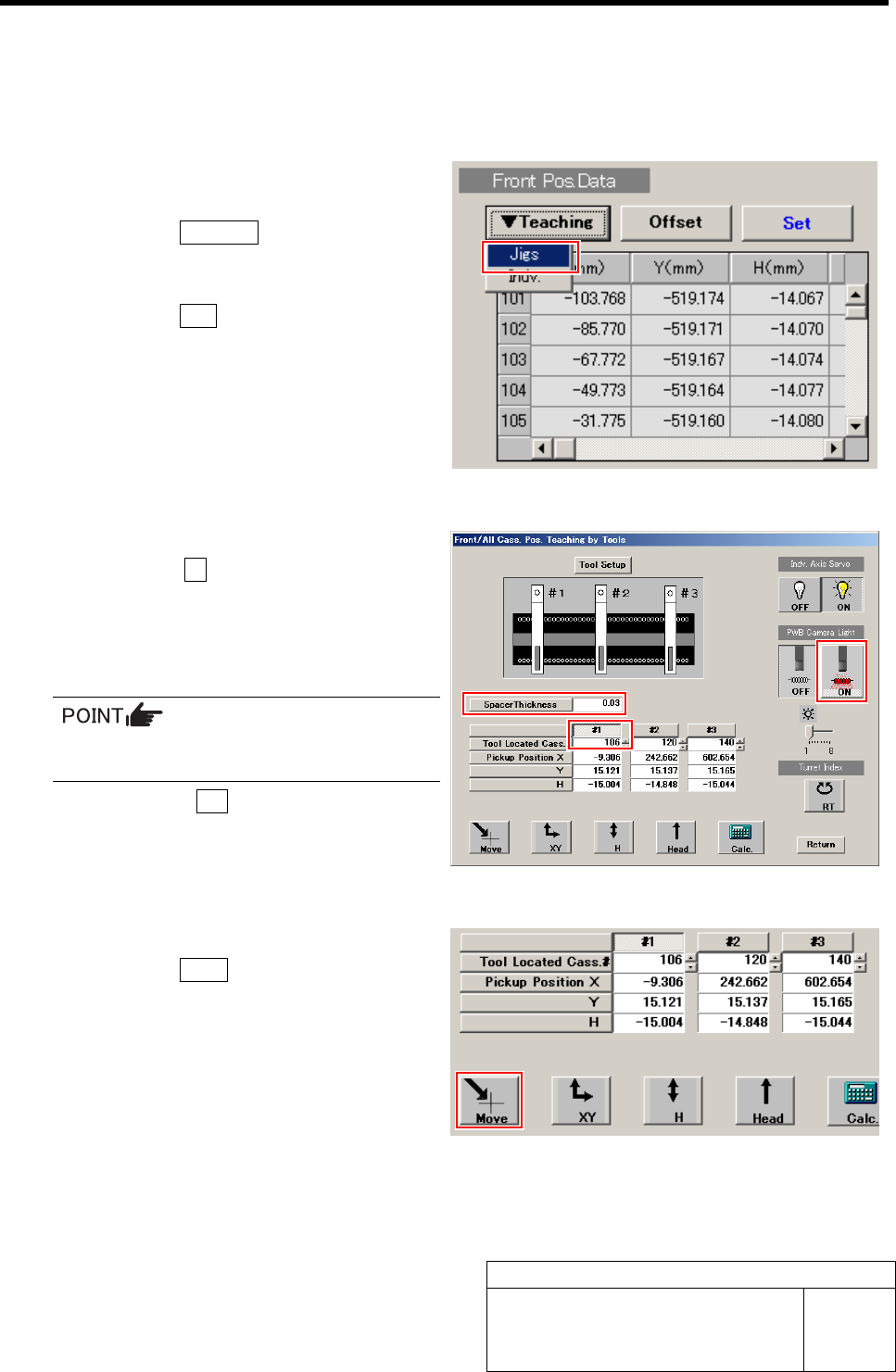
XY Position Data Teaching
[Procedure]
1 Display a Front/All Cass. Pos. Teaching by
Tools screen.
1. Click the Teaching button on the Front
Pos. Data to display a drop down
menu.
2. Click the Jigs in the drop down menu.
The Front/All Cass. Pos. Teaching by Tools
screen is displayed.
2 Set the jig.
1. Click the #1 and input “106” in input
box for Tool Located Cass.
2. Input thickness of “0.03” of thickness
gauge used for H axis position data
teaching.
The value of the spacer thickness becomes
offset value when acquiring H coordinate.
3. Click the ON button on the PWB
camera light.
The PWB camera light lights up.
3 Move the PWB camera to the pickup point.
1. Click the Move button.
Move screen is displayed.