SI-F130 Manual(EN)_jpg_ Rev1.pdf - 第87页
Software Limit Setup HLF-10315-01 Soft w are Limit Setup SHEET 2/7 [Procedure] 1 Check the cassette pickup positio n data. 1. Click in an order of M/C SETUP menu Î P ARTS SUPPL Y tab. P AR TS SUPPL Y screen is displayed.…
Software Limit Setup
HLF-10315-01
Software Limit Setup
SHEET
1/7
Software Limit Setup
[Necessary jigs]
• Do not use jig.
[Procedure]
In order to set up software limit, it is necessary to change the default value at first so that the
software limit does not function.
Before setting up the software limit, change the default values of the software limit according to the
following procedure.
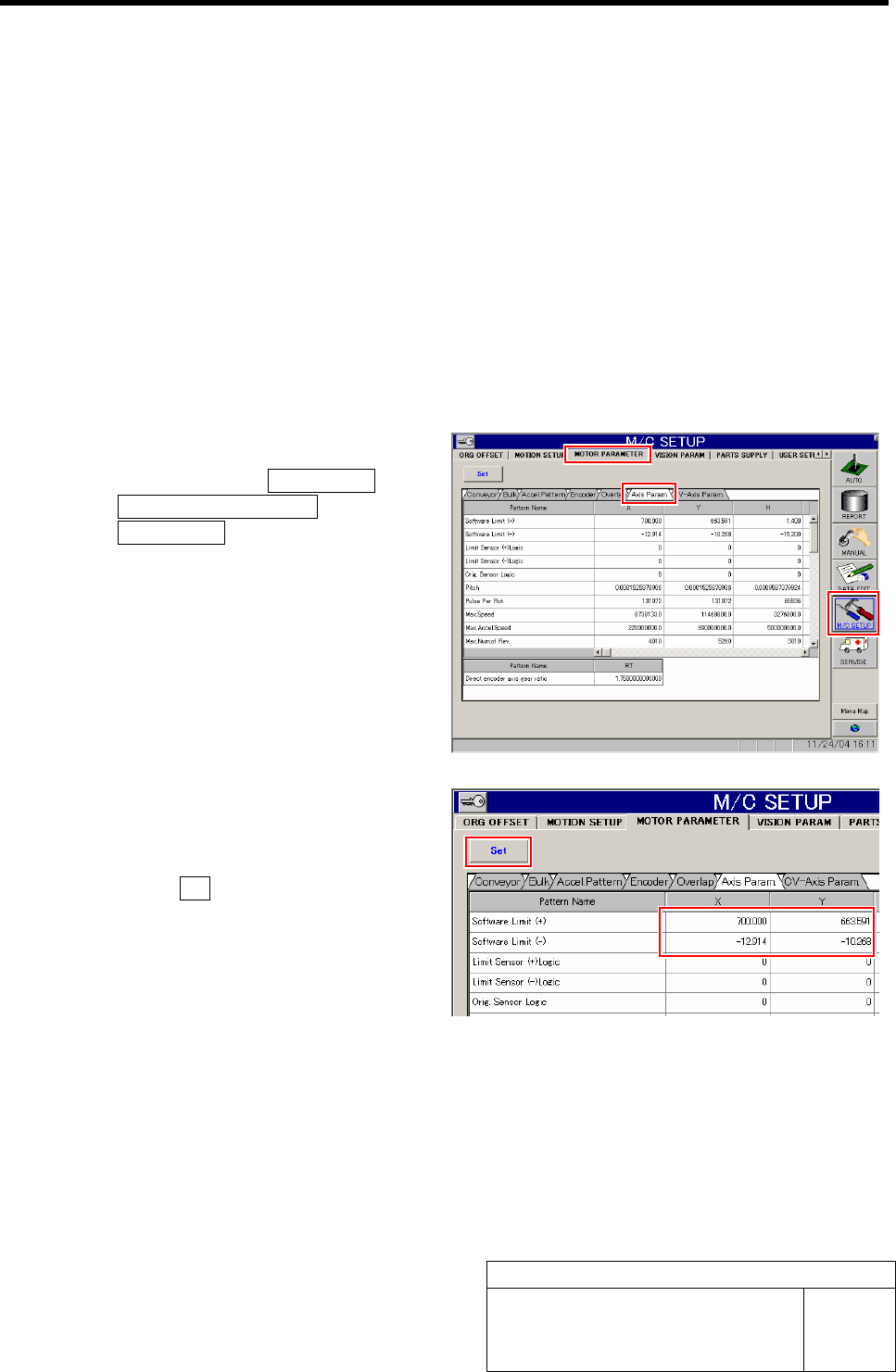
1 Change the default value of the software.
1. Click in an order of M/C SETUP men
ÎMOTOR PARAMETER tab
ÎAxis Param. tab.
Axis Parameter screen is displayed.
2. Input values for which “100” is respec-
tively added to software limit +/- val-
ues of XY axis.
3. Click the Set button.
The updated software limit values are saved.
Software Limit Setup
HLF-10315-01
Software Limit Setup
SHEET
2/7
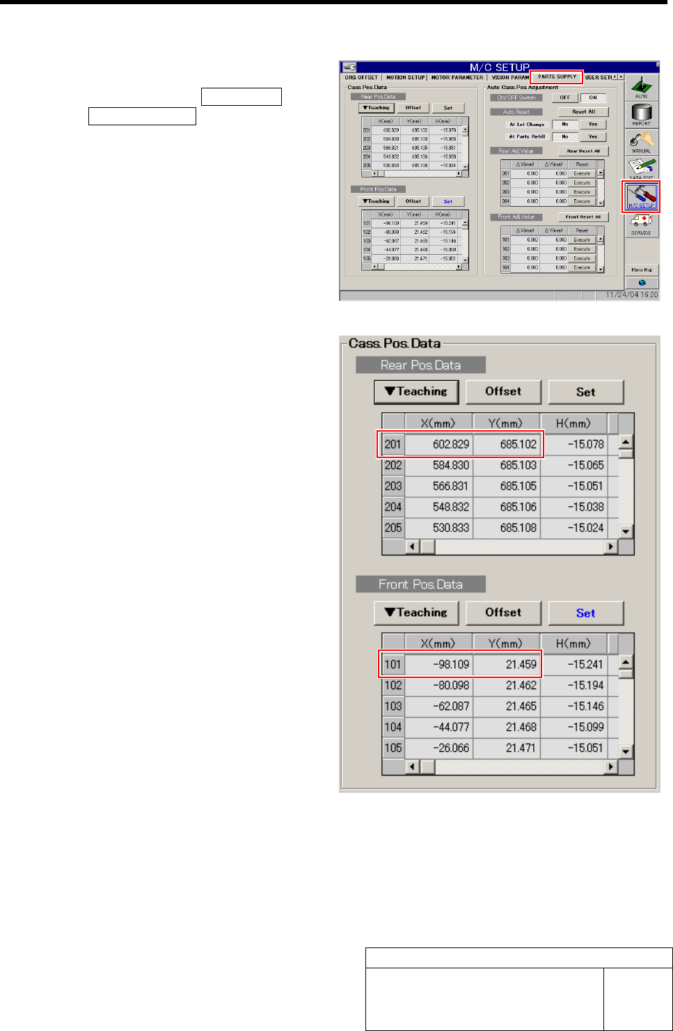
[Procedure]
1 Check the cassette pickup position data.
1. Click in an order of M/C SETUP menu
ÎPARTS SUPPLY tab.
PARTS SUPPLY screen is displayed.
2. Make a memo of XY position data of
cassette position “101” and “201” dis-
played on the cassette position data
table.
3. Scroll down the cassette position data
table and make a memo of XY position
data of cassette positions “140” and
“240”.
Software Limit Setup
HLF-10315-01
Software Limit Setup
SHEET
3/7
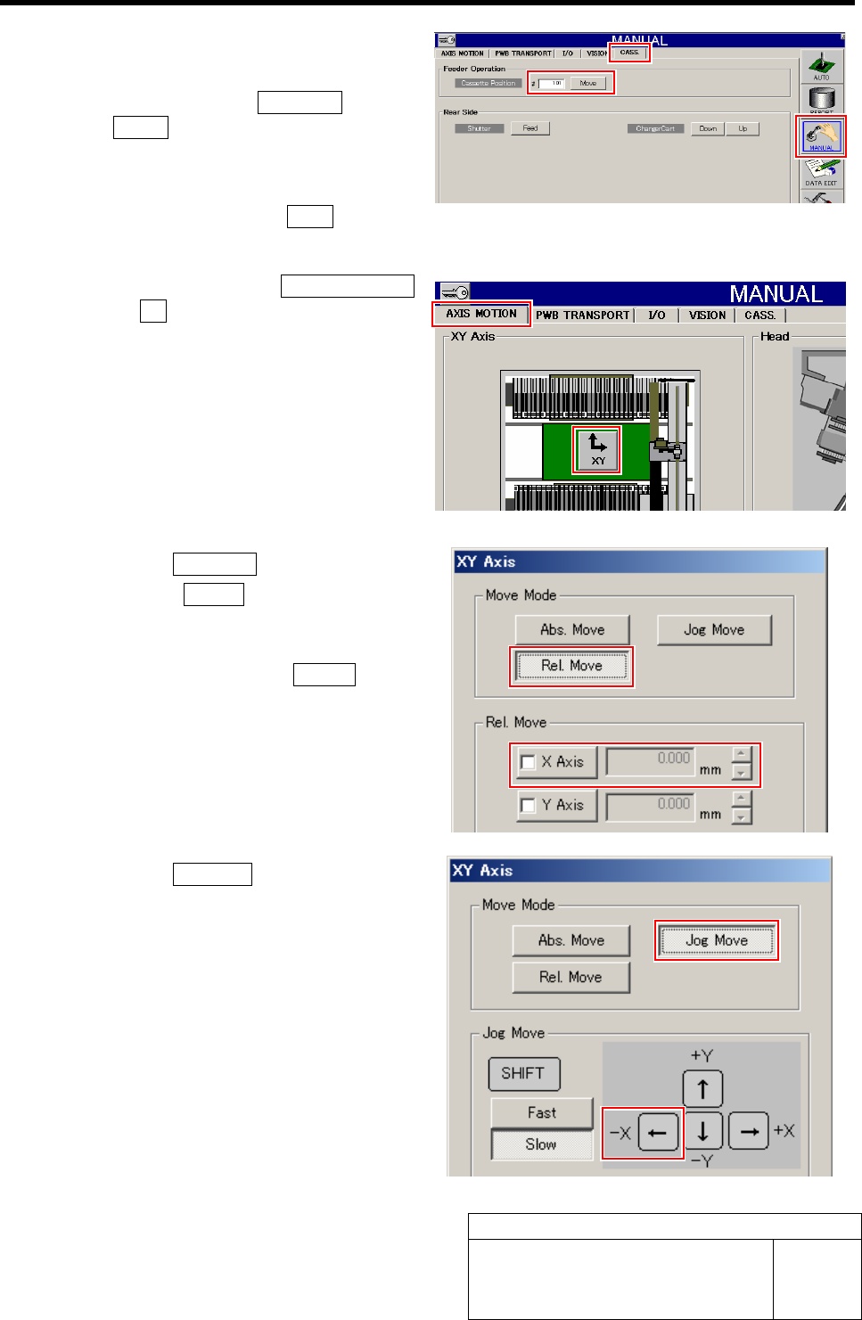
2 Check the X position data of over-travel
sensor (OT) of X-CCW.
1. Click in an order of MANUAL menu
ÎCASS. tab.
Cassette operation screen is displayed.
2. Input “101” into the cassette position
input box and click the Move button.
The head moves to the cassette position “101”.
3. Click in an order of AXIS MOTION
tabÎXY button.
XY Axis screen is displayed.
4. Click the Rel. Move button.
5. Click the X Axis button in the Rel.
Move.
6. Input “-3.000” into number input box
for X axis and press the START button
on the operation panel.
The X axis relatively moves from the position of
cassette 101 by -3mm.
7. Click the Jog Move button.
8. Press the left cursor key one time by
one by slow Jog Move to move the X
axis in negative direction.
When the X axis is moved to the over-travel po-
sition, alarm is displayed.