00197454-01_AI_Portal_40mm_TwinVHF_SX12_de_en - 第108页
assembly Gantry Preparations 3.2.4 Transportation Lo cks and Tilt Guard 108 Reconfiguration Kit Twin VHF with Gantry Reconfiguration Ki t T w i n V H F m i t P o r - 3.2.4 3 . 2 . 4 T r a n s p o r t a t io n L o c k s a…
assembly
3.2.3 Locking and Transporting the Gantry Carrier Gantry Preparations
Reconfiguration Kit Twin VHF with Gantry Reconfiguration Kit Twin VHF mit Portal 107
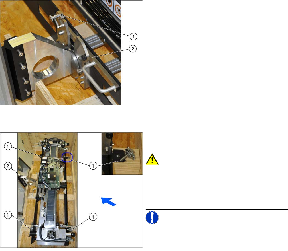
Locking the gantry carrier correctly
Securing the gantry in the transportation crate
► Check that the lever (2) on the lock (1) has engaged
properly.
► To open, press the lock backwards and then press
the lever downwards. This opens the lock.
► The gantry is fixed with 4 screws (1) in the transpor
-
tation crate. Loosen these screws.
CAUTION!
Only transport the gantry with the gantry lift when the
arms are locked!
► Move the gantry lift upwards and carefully lift the gan
-
try out of the transportation crate.
NOTICE!
The placement head must be in the center of the gantry.
This ensures that the load is distributed evenly during
transportation.
assembly
Gantry Preparations 3.2.4 Transportation Locks and Tilt Guard
108 Reconfiguration Kit Twin VHF with Gantry Reconfiguration Kit Twin VHF mit Por
-
3.2.4
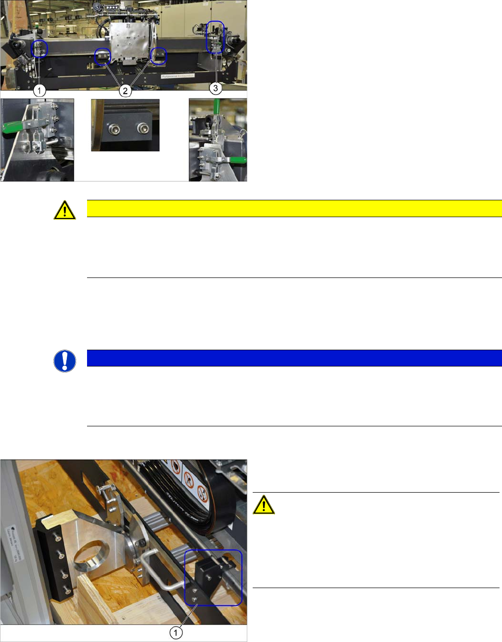
3.2.4 Transportation Locks and Tilt Guard
Transportation Locks and Tilt Guard
► Swing the green lever upwards and swivel the transportation lock to one side.
► There is another lever at (3). Swing the green lever upwards and remove it.
► Loosen the 2 screws fastening the transportation locks (2) to the head plate in each case and remove
both locks.
Tilt guard on the gantry carrier
The gantry is locked with 3 transportation locks (1) and
(3) at the gantry carrier. In addition, the head plate has
two transportation locks (2) for the placement head.
CAUTION
Docking
► Flap down the transportation lock plates right before the docking.
► Make sure that the gantry does not slide of the gantry carrier during rerailing respectively
derailing and that the tilt guard is suspended in order to hold the gantry in position.
NOTICE
Storing the transportation locks
If the gantry is transported or packed back into the transportation crate, you need to refit the
transportation locks.
► Place the transportation locks in the crate for later usage.
The gantry is also fitted with a tilt guard (1) on the gantry
carrier.
CAUTION!
Tilt guard on the gantry carrier
When the tilt guard is open, the gantry could fall off the
gantry carrier.
Only open the tilt guard once you have hooked the gantry
carrier onto the machine docking unit.
assembly
3.2.5 Fitting the HCUs and HCU Base Adapter Assembly Twin VHF
Reconfiguration Kit Twin VHF with Gantry Reconfiguration Kit Twin VHF mit Portal 109
3.2.5
3.2.5 Fitting the HCUs and HCU Base Adapter
Fitting the HCUs and HCU Base Adapter
► Fit the HCUs onto the base adapter and then fit the base adapter onto the gantry.
Please read section "4.1.3 Replacing the Head Adapter for the HCU and the HCU" [ ➙ 136] and the
relevant chapter in the service manual for your machine.
3.3
3.3 Assembly Twin VHF
Assembly Twin VHF
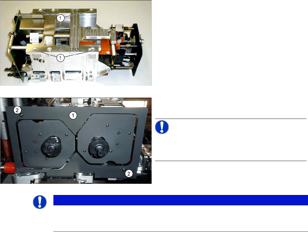
The Twin VHF is fitted to the gantry before the gantry is installed.
Assembly Twin VHF
The Twin VHF consists of 2 identical Twin segments, which are fitted at an angle of 180°.
Each module is fixed with 4 screws to the head plate and
is positioned with two pins.
► Lift the first Twin VHF module into position and fasten
this into place using a long Allen key. Use
4 M4x14 (1) screws.
► Repeat this step for the second Twin VHF module.
► Fit the camera screen (1). This is fastened into place
using two black screws (2).
NOTICE!
Only use these screws to fix the camera screen. This pre
-
vents reflection when measuring components with the
stationary camera.
NOTICE
Hose and cable guidance
When performing the following steps, pay attention to the correct running of hoses and cables.
Refer to the diagrams for guidance.