00197454-01_AI_Portal_40mm_TwinVHF_SX12_de_en - 第115页
assembly 3.5.1 Replacing/Fitting the End Position Buffers Fitting the Gantry Reconfiguration Kit Twin VHF with Gantry Re configuration Kit Twin VHF mit Portal 115 Installation Buffer types: 1. Standard: long buffer with …
assembly
Fitting the Gantry 3.5.1 Replacing/Fitting the End Position Buffers
114 Reconfiguration Kit Twin VHF with Gantry Reconfiguration Kit Twin VHF mit Por
-
3.5.1
3.5.1 Replacing/Fitting the End Position Buffers
Replacing/Fitting the End Position Buffers
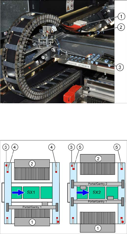
Overview
► Carefully place the flat ribbon cable (1) and the pneu
-
matic connections (2) over the gantry.
► Remove the black plastic foil. A cable tie fixes the
black plastic foil to the trailing cable (1).
When upgrading from an SX1 to an SX2, you need to fit
the short end position buffers at location 2.
When downgrading from an SX2 to an SX1, fit the buffer
with distance pipe at location 2.
When fitting a 40 mm gantry, you need to fit the buffer
with distance pipe at location 2 of the SX1. (Buffer labe
-
ling: "LOC2, VHF SX1")
1. Location 1
2. Location 2
3. Security switch
4. Buffer with distance pipe at an SX1
Standard: 226.5 mm
Twin VHF: 174 mm
5. Short buffer on an SX2 (standard and Twin VHF)
assembly
3.5.1 Replacing/Fitting the End Position Buffers Fitting the Gantry
Reconfiguration Kit Twin VHF with Gantry Reconfiguration Kit Twin VHF mit Portal 115
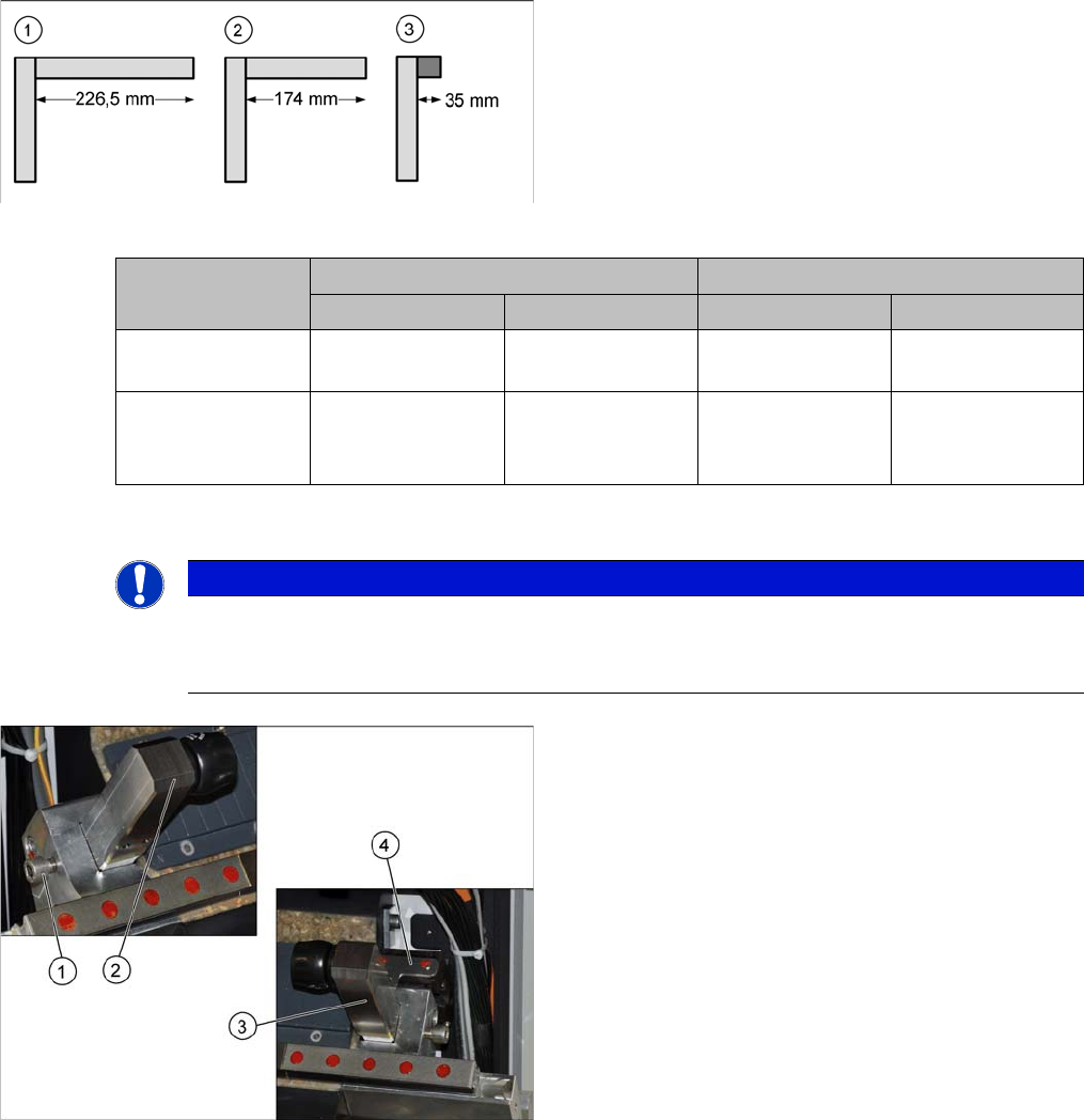
Installation
Buffer types:
1. Standard: long buffer with distance pipe for location 2
of an SX1 (226.5 mm)
2. Twin VHF: buffer with shortened distance pipe
[03105259-xx] for location 2 of an SX1 (174 mm)
Buffer labeling: "LOC2, VHF SX1"
3. Standard and Twin VHF: short buffer with rubber
damper for both locations on an SX2 (35 mm)
Machine SX 1 SX2
Location 1 Location 2 Location 1 Location 2
Standard 35 mm rubber
dampers
226.5 mm
distance pipe
35 mm rubber
dampers
35 mm rubber
dampers
40 mm gantry for
Twin VHF
35 mm rubber
dampers
174 mm distance
pipe (shortened)
LOC2, VHF SX1
35 mm rubber
dampers
35 mm rubber
dampers
NOTICE
Holder and distance pipe
► You might need to fit the holder from one distance pipe onto the other distance pipe. When
doing so, hand-tighten the distance pipe on the holder.
► Fit the end position buffer (2) to the left side.
► Fit the end position buffer (3) to the right side. The
safety switch (4) for the buffer monitoring function
must engage in the Schmersal switch.
► Tighten the fastening screws (1) for the buffers with a
torque of 14 Nm.
assembly
Trailing Cable Connection 3.5.1 Replacing/Fitting the End Position Buffers
116 Reconfiguration Kit Twin VHF with Gantry Reconfiguration Kit Twin VHF mit Por
-
3.6
3.6 Trailing Cable Connection
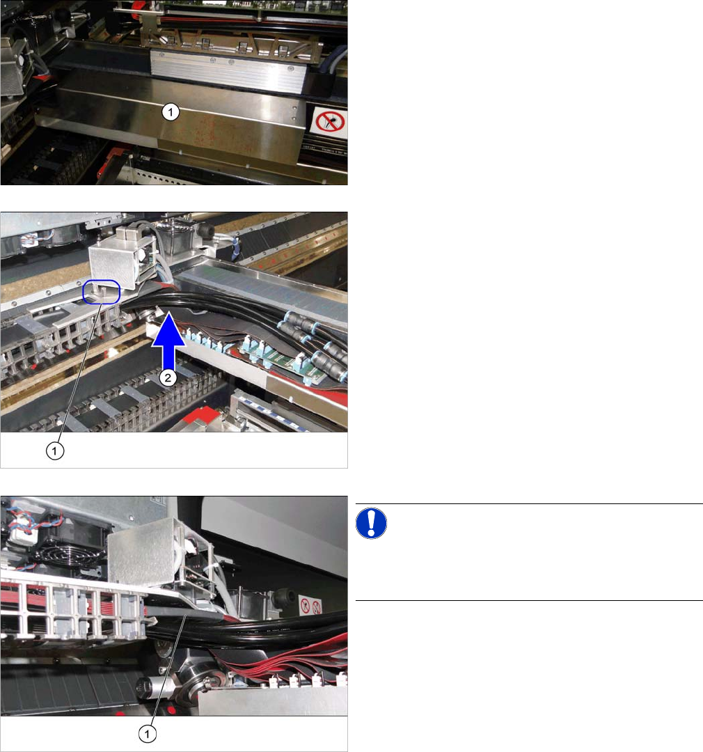
Trailing Cable Connection
► Remove the cover (1) over the gantry interface. To do
this, loosen the two fastening screws on the right side
and carefully open the bottom left pushbutton.
► Fit the trailing cable holder (1) from below, to the gan
-
try distributor holder. See the following section.
► Carefully place the flat ribbon cable and the pneumat
-
ic hoses to one side (2).
► Make sure you do not damage the cables and hoses.
► Take care that the alignment is correct and that all ca
-
bles and hoses are run above one another and even
-
ly.
NOTICE!
When fitting the trailing cable, make sure that the heat-
shrinkable sleeve (1) protects the flat ribbon cable under
the Y sensor module holder.