00197454-01_AI_Portal_40mm_TwinVHF_SX12_de_en - 第117页
assembly 3.5.1 Replacing/Fitting the End Position Buffers Trailing Cable Connection Reconfiguration Kit Twin VHF with Gantry Re configuration Kit Twin VHF mit Portal 117 Trailing cable mount Restore the electrical and pn…
assembly
Trailing Cable Connection 3.5.1 Replacing/Fitting the End Position Buffers
116 Reconfiguration Kit Twin VHF with Gantry Reconfiguration Kit Twin VHF mit Por
-
3.6
3.6 Trailing Cable Connection
Trailing Cable Connection
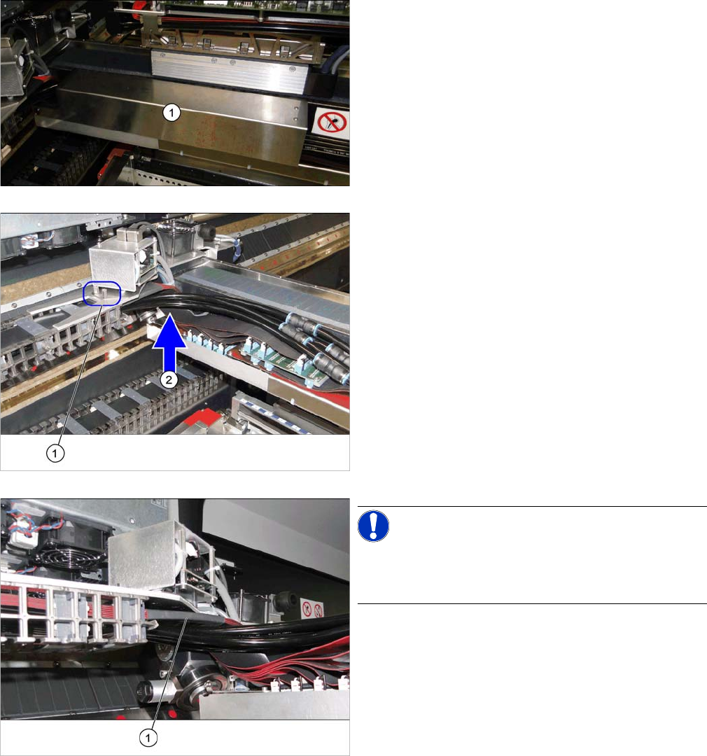
► Remove the cover (1) over the gantry interface. To do
this, loosen the two fastening screws on the right side
and carefully open the bottom left pushbutton.
► Fit the trailing cable holder (1) from below, to the gan
-
try distributor holder. See the following section.
► Carefully place the flat ribbon cable and the pneumat
-
ic hoses to one side (2).
► Make sure you do not damage the cables and hoses.
► Take care that the alignment is correct and that all ca
-
bles and hoses are run above one another and even
-
ly.
NOTICE!
When fitting the trailing cable, make sure that the heat-
shrinkable sleeve (1) protects the flat ribbon cable under
the Y sensor module holder.
assembly
3.5.1 Replacing/Fitting the End Position Buffers Trailing Cable Connection
Reconfiguration Kit Twin VHF with Gantry Reconfiguration Kit Twin VHF mit Portal 117
Trailing cable mount
Restore the electrical and pneumatic connections
Connections established
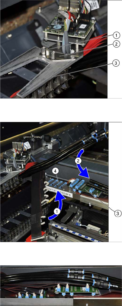
1. Two hexagon spacer bolts M4 x 10 mm.
2. Gantry board holder
3. Trailing cable holder
► Loosen the two hexagon spacer bolts M4 x 10 mm on
the trailing cable holder.
► Hold the trailing cable holder from below, on the gan
-
try board holder.
► Screw the two hexagon spacer bolts from above, into
the trailing cable holder.
► Secure the two hexagon spacer bolts with Loctite
241.
► First connect the 7 flat ribbon cables (1) to the boards
for the gantry interface of the X axis (3) and the gantry
interface of the Y axis (4). The sequence depends on
the different cable lengths. Work your way from back
to front.
► Remove the dummy plugs from the pneumatic hose
couplings.
► Connect the four pneumatic connections for the trail
-
ing cable to the gantry connections (2). The se
-
quence depends on the different hose lengths..
This diagram shows the precisely run and correctly ar
-
ranged connections.
assembly
Trailing Cable Connection 3.5.1 Replacing/Fitting the End Position Buffers
118 Reconfiguration Kit Twin VHF with Gantry Reconfiguration Kit Twin VHF mit Por
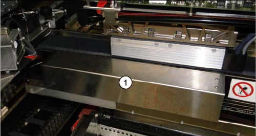
-
► Fit the cover (1) over the gantry interface.