00197454-01_AI_Portal_40mm_TwinVHF_SX12_de_en - 第123页
assembly 3.7.6 Fitting the Nozzle Changer and Options Final Work Reconfiguration Kit Twin VHF with Gantry Re configuration Kit Twin VHF mit Portal 123 Hotlink card [03052135-xx] Hotlink card [03052135 -xx] 3.7.6 3 . 7 . …
assembly
Final Work 3.7.5 Checking the Camera Cable
122 Reconfiguration Kit Twin VHF with Gantry Reconfiguration Kit Twin VHF mit Por
-
3.7.5
3.7.5 Checking the Camera Cable
Checking the Camera Cable
► Check whether the camera cable is connected to the hotlink card on the box PC. Make sure that the
connections are correct. (See labelling on hotlink card).
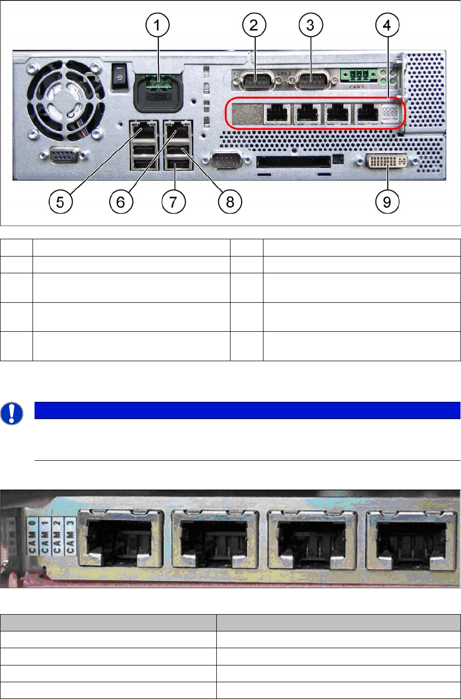
Hotlink card [03032343-xx]
Hotlink card [03032343-xx]
(1) Power supply DC 24 V (2) CAN 1 on the CAN bus card
(3) CAN 2 on the CAN bus card (4) Hotlink card
(5) LAN 2 – connection to Vision computer
(optional second BoxPC)
(6) LAN 1 – connection to SIPLACE Pro
(connection to line hub)
(7) USB 0 – connection for keyboard/touch
-
screen (connection to USB hub)
(8) USB 2 – connection for an external DVD
drive
(9) DVI/VGA monitor connection
(connection to video multiplexer)
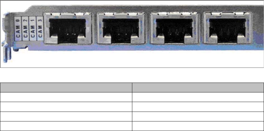
NOTICE
Hotlink card:
Pay attention to the connections of the different hotlink cards, recognizable due to the sticker
(see the following explanation)!
Connection on the hotlink card Designation
CAM0 Head cameras gantry 1
CAM1 Head cameras gantry 2
CAM2 Stationary cameras gantry 1
CAM3 Stationary cameras gantry 2
assembly
3.7.6 Fitting the Nozzle Changer and Options Final Work
Reconfiguration Kit Twin VHF with Gantry Reconfiguration Kit Twin VHF mit Portal 123
Hotlink card [03052135-xx]
Hotlink card [03052135-xx]
3.7.6
3.7.6 Fitting the Nozzle Changer and Options
Fitting the Nozzle Changer and Options
Installing the required nozzle changer (head-related)
► See also the "Nozzle Changer Assembly Guide for SIPLACE SX series German/English"
[00196578-xx].
Fitting the stationary cameras (optional)
► See also the "Stationary Camera Type 33 Assembly Guide German/English" [00196608-xx] and the
"Stationary Camera Type 25 Assembly Guide German/English" [0094554-xx].
Fitting the component reject bin query (optional)
► See also the "Reject Bin Query Assembly Guide for SIPLACE SX1/SX2 German/English"
[00196615-xx].
Taking into account the component trolley docking unit inner/outer
► See also the "SIPLACE SX1/SX2 Service Manual" [German: 00196496-xx] [English: 00196497-xx]
Connection on the hotlink card Designation
CAM0 Head cameras gantry 1
CAM2 Stationary cameras gantry 1
CAM1 Head cameras gantry 2
CAM3 Stationary cameras gantry 2
assembly
Final Work 3.7.7 Performing Calibration
124 Reconfiguration Kit Twin VHF with Gantry Reconfiguration Kit Twin VHF mit Por
-
3.7.7
3.7.7 Performing Calibration
Performing Calibration
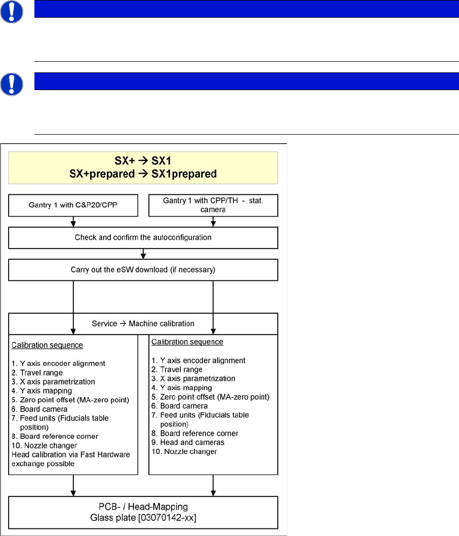
Overview
The SW704 divides the mapping data and then merges them during the gantry upgrade. In most cases
this means that only a brief calibration procedure needs to be performed (see Fast Hardware Exchange
and flow diagram).
If gantry 1 is fitted, you need to perform PCB/component mapping with the glass plate, irrespective of
the head configuration (gantry 1 is the master gantry).
NOTICE
TH gantry at location 2
If there is a TH gantry at location 2 (gantry 2), the PCB mapping data must be present. Com
-
ponent mapping can then be performed using the aluminum plate.
NOTICE
Long Board Option
If a gantry is installed on a machine with Long Board Option (LBO), this gantry has to be
mapped using the "Mapping with LBO" button.