00197454-01_AI_Portal_40mm_TwinVHF_SX12_de_en - 第132页
assembly Checklist 3.7.8 Modifications in SIPLACE Pro 132 Reconfiguration Kit Twin VHF with Gantry Reconfiguration Ki t T w i n V H F m i t P o r -

assembly
3.7.8 Modifications in SIPLACE Pro Checklist
Reconfiguration Kit Twin VHF with Gantry Reconfiguration Kit Twin VHF mit Portal 131
3.8
3.8 Checklist
Checklist
► Put this check list in the machine logbook.
Gantry fitted (upgrade)
Step Action Who?
1 Gantry fitted? Customer in line with assembly
guide
2 Are the modules fitted in the correct positions? Customer in line with assembly
guide
3 Are the correct end position buffers fitted? Customer in line with assembly
guide
4 Has the trailing cable been fitted correctly? Customer in line with assembly
guide
5 Does the trailing cable run parallel? Customer in line with assembly
guide
6 Is the gantry coding correct? Customer in line with assembly
guide
7 Is the stationary camera (optional) fitted? Customer in line with assembly
guide
8 Are the camera connections connected to the box PC? Customer in line with assembly
guide
9 Has the nozzle changer been fitted? Customer in line with assembly
guide
10 Is the reject bin fitted? Customer in line with assembly
guide
11 Have all tools been removed from the machine? Customer in line with assembly
guide
12 Are the doors screwed? Customer in line with assembly
guide
13 Is the machine switched on and ready for operation? Customer in line with assembly
guide
14 Have all calibration steps been performed? Customer in line with assembly
guide
Date Signature
assembly
Checklist 3.7.8 Modifications in SIPLACE Pro
132 Reconfiguration Kit Twin VHF with Gantry Reconfiguration Kit Twin VHF mit Por
-
Appendix
4.1.1 Installation Positions on the Twin VHF Head Plate Excerpts from the Service Manual
Reconfiguration Kit Twin VHF with Gantry Reconfiguration Kit Twin VHF mit Portal 133
4
4 Appendix
Appendix
4.1
4.1 Excerpts from the Service Manual
Excerpts from the Service Manual
The following chapters are excerpts from the service manual. For more information, refer to the full ser
-
vice manual for your machine.
4.1.1
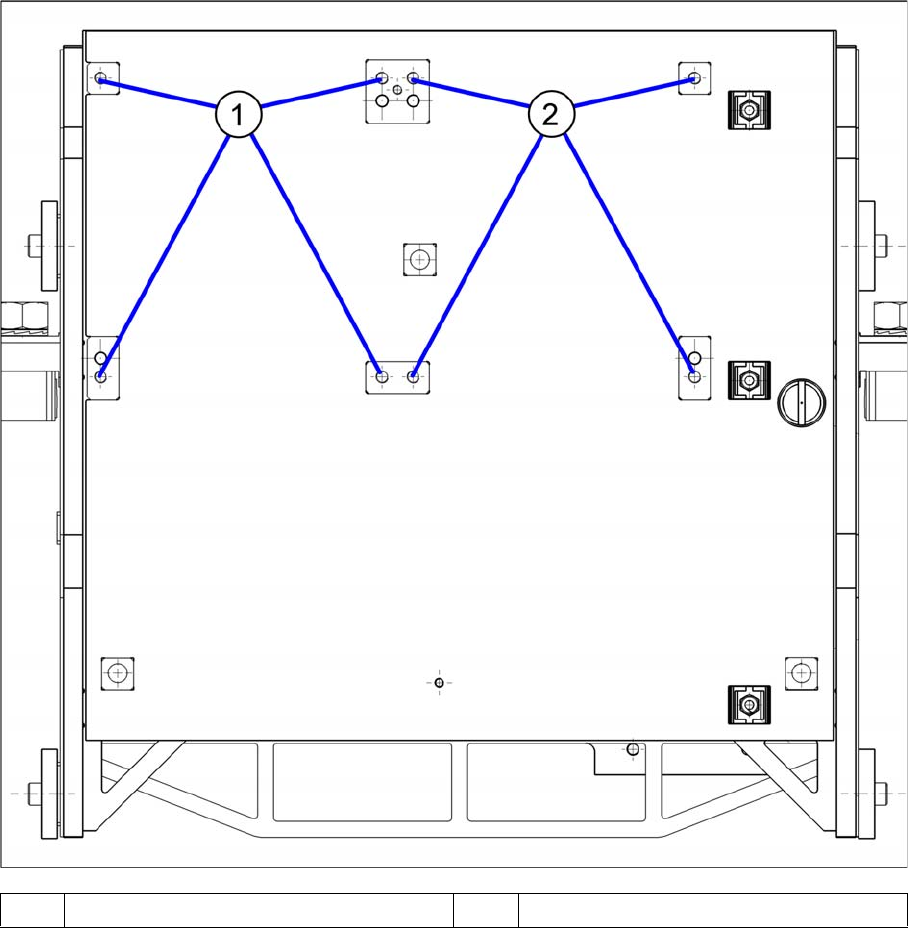
4.1.1 Installation Positions on the Twin VHF Head Plate
Installation Positions on the Twin VHF Head Plate
1 Installation position Twin VHF segment 1 2 Installation position Twin VHF segment 2