EUKYX-199-4110_G5S2_Instruction_Vol4_E.pdf - 第115页
EUKYX 1-66 199-4100 5.5 Cleaning of high-speed nozzle hole part with pin gauge 5.5 Cleaning of h igh-speed nozzle hole p ar t with pin gauge Confirm the c log of the no zzle ho le wi th the magn ifying g lass . When the …
EUKYX
1-65199-4100
5.4 Method of Blow air
5.4 Method of Blow air
• Remove dust and dirt etc.
Remove slight dust and dirt by blowing air or wiping off.
Clean the tapered area of the vacuum nozzle with a lens cleaning cloth.
Use clean, dry, and non-lubricated air for blowing air.
F4A49
NOTICE
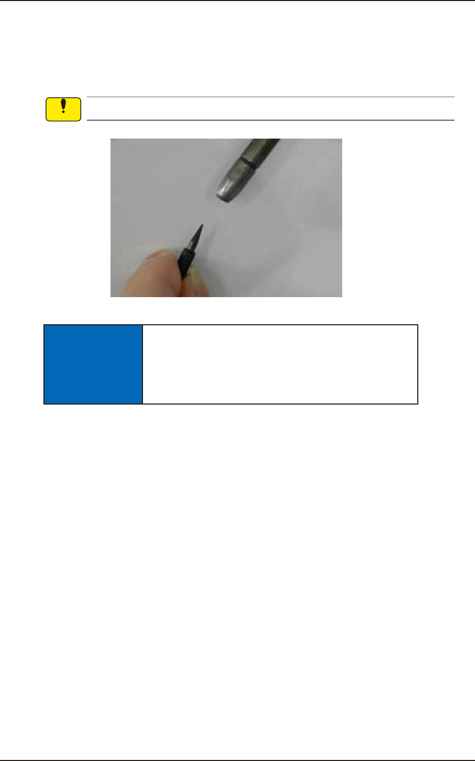
When blowing air to the nozzle, make sure to blow
from the nozzle end section.
If blowing air from the clamp claw section, the clamp
claw might be damaged.
Notice
EUKYX
1-66199-4100
5.5 Cleaning of high-speed nozzle hole part with pin gauge
5.5 Cleaning of high-speed nozzle hole part with pin gauge
Confirm the clog of the nozzle hole with the magnifying glass.
When the clog is found, clean it with the pin gauge.
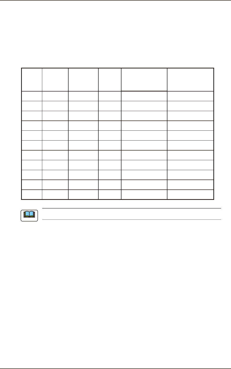
• Select pin gauge
The pin gauge to be used varies depending on the type of a high-speed nozzle.
Select it referring to the combination shown below.
Unit : mm
Nozzle
ID
Diameter
(center
hole
diameter)
Diameter
(minimum
hole
diameter)
Pin
gauge
size
Part Number
Direction of pin
gauge insertion
HG24C
∅
0.1
∅
0.08
∅
0.08 KYA-M7702-A0 Nail side, Head side
HG33C
∅
0.2
∅
0.08
∅
0.12 K YA-M7703 -A0 Nail side, Head side
HG52C
∅
0.4
∅
0.25
∅
0.2 K YA-M7705 -A0 Nail side, Head side
HG82C
∅
0.7
∅
0.35
∅
0.3 K YA-M7708 -A0 Head side (a)
HV82C
∅
0.7
∅
0.35
∅
0.3 K YA-M7782-A0 Nail side, Head side
HG13C
∅
0.9
∅
0.9
∅
0.6 KYB-M771J-A0 Head side (a)
HV13C
∅
0.9
∅
0.9
∅
0.6 K YA-M7713 -A0 Nail side, Head side
HG14C
∅
1.1
∅
1.1
∅
0.8 KYB-M771K-A0 Head side (a)
HV14C
∅
1.1
∅
1.1
∅
0.8 K YA-M7714-A0 Nail side, Head side
HG15C
∅
2.0
∅
1.1
∅
0.8 KYF-M77G5-A0 Head side (a)
HV15C
∅
2.0
∅
1.1
∅
0.8 K YA-M7715 -A0 Nail side, Head side
(a) Pin gauge can not be inserted from nail side.
Note
EUKYX
1-67199-4100
5.5 Cleaning of high-speed nozzle hole part with pin gauge
• Method of cleaning high-speed nozzle hole
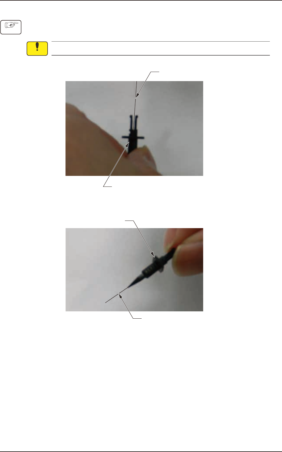
(1) Firmly have the high-speed nozzle as shown in the figure below.
Insert it while matching a pin gauge center axis to a center axis of a high-speed nozzle.
When a center axis shifts, the nozzle tip might be damaged.
Pin gauge
High-speed nozzle
F4A50
(2) Put out the pin gauge from the head of the high-speed nozzle.
High-speed nozzle
Pin gauge
F4A51
Procedure
Notice