EUKYX-199-4110_G5S2_Instruction_Vol4_E.pdf - 第80页
EUKYX 1-31 199-4100 4.6 Cutter Section (5 ) Remove di rt an d dust in the cut ter unit with a vacuum c leane r . Use a vacuu m cleaner no z zle for narrow spaces . Shape of recommended vacuum cleaner nozzle F4A28 Cutter …
EUKYX
1-30199-4100
4.6 Cutter Section
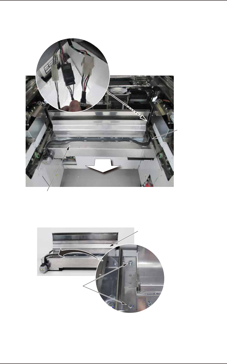
(3) Pull out the cutter unit main body forward. Remove 3 unit connection connectors. At this
point, make sure not to tear off the connector cables by pulling them forcibly. Additionally,
take care that the connector cables are not trapped when returning the unit to the original
position.
Connection connectors (3 pcs)
Connector
cable
Front
Cutter unit main body
F4A27C
(4) Remove hex socket head cap screws mounting the upper slope (2 each on the left and
right). Detach the upper slope.
Hex socket head cap screws
Upper slope
F4A27D
EUKYX
1-31199-4100
4.6 Cutter Section
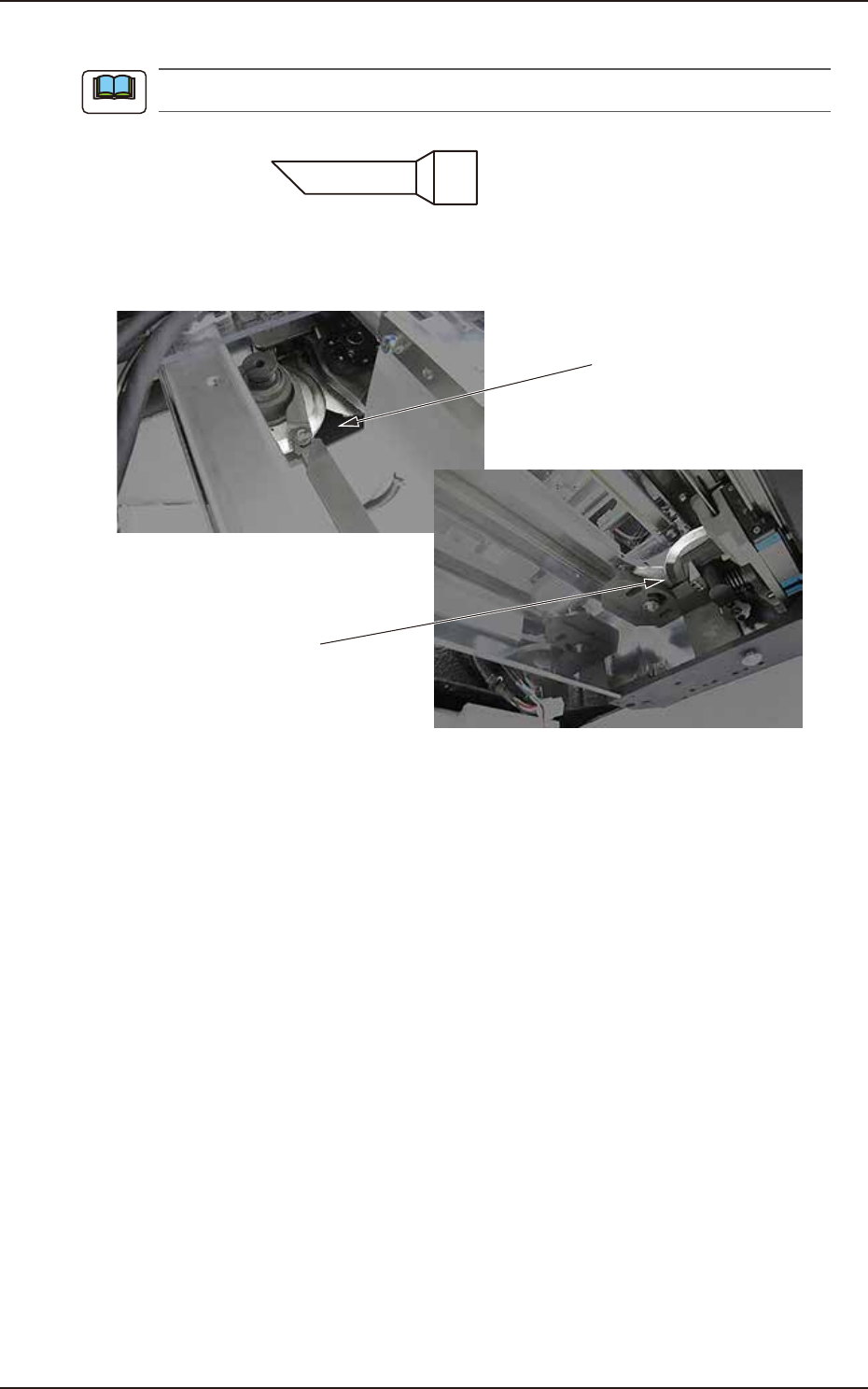
(5) Remove dirt and dust in the cutter unit with a vacuum cleaner.
Use a vacuum cleaner nozzle for narrow spaces
.
Shape of recommended
vacuum cleaner nozzle
F4A28
Cutter blade (bottom surface)
Cutter blade
(top surface)
F4A27E
Note
EUKYX
1-32199-4100
4.6 Cutter Section
4.6.2 Cutter Unit Lubrication
Cycle: Every 3 Months (Required Time : 40 minutes)
Grease: DAPHNE GREASE MP No. 1
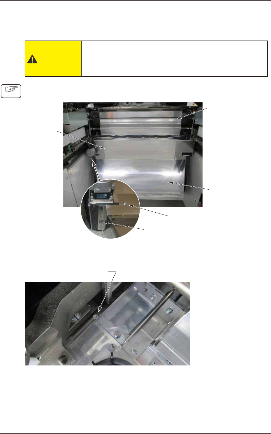
CAUTION
After making sure that the power supply has been stopped,
start maintenance. During maintenance, do not touch the
cutter blade.
(1) Remove the truss head screws (1 each on left and right) mounting the lower slope. Loosen
the truss head screws at the bottom (1 each on left and right). Detach the lower slope.
Cutter unit
Upper slope
Lower slope
Truss head screw (front side)
Truss head screw (Bottom side)
F4A27AA
(2) Remove hex socket head cap screws mounting the cutter unit (1 each on left and right).
Hex socket head cap screw
F4A27B
Procedure