EUKYX-199-4110_G5S2_Instruction_Vol4_E.pdf - 第89页
EUKYX 1-40 199-4100 4.6 Cutter Section Replac ing cla mp lev er C yc le : 1 year (Required Time : 60 minutes) ( 1 ) Remove the cut te r unit from the main unit . Refer to “ 4.6. 2 Cutte r Unit Lubrication ” for th e proc…
EUKYX
1-39199-4100
4.6 Cutter Section
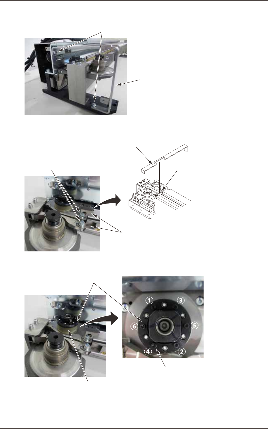
(7) Remove the hex socket head cap screws (2 each on left and right) mounting the frame
brackets. Remove frame brackets and the plates.
Frame bracket
Hex socket head cap screws
F4A81C
(8) Hang and clamp the clamp lever mounting jig on 2 clamp lever mounting bolts closing the
clamp lever.
Clamp lever mounting jig
Mounting position
Clamp lever
Clamp lever mounting bolts
F4A81D
(9) Loosen 6 hex socket head cap screws mounting the seal cover with a wrench in the order
of 1 to 6. Remove hex socket head cap screws. Replace the flat ring.
Hex socket head cap screw
Seal cover
Flat ring
F4A81E
(10) Return the seal cover to the original position. Install 6 hex socket head cap screws in the
order of 1 to 6. At this time, install the screws with the tightening torque 18.6 to 22.6 Ncm
(1.9 to 2.3 kgfcm) with a torque driver included in the line accessories.
EUKYX
1-40199-4100
4.6 Cutter Section
Replacing clamp lever
Cycle: 1 year (Required Time : 60 minutes)
(1) Remove the cutter unit from the main unit.
Refer to “4.6.2 Cutter Unit Lubrication” for the procedure.
(2) Remove the upper slope from the cutter unit.
Refer to “4.6.2 Cutter Unit Lubrication” for the procedure.
(3) Remove the rear cover.
Refer to “4.6.2 Cutter Unit Lubrication” or the procedure.
(4) Remove 5 hex socket head cap screws mounting the fluorine sheet assembly from the cutter
unit. Remove the fluorine sheet assembly.
Refer to “Replacing fluorine sheet” in “4.6.3 Parts replacement of the cutter unit” for the
procedure.
(5) Remove 2 truss head screws mounting the polycarbonate plate and the cable.
Remove the polycarbonate plate.
Refer to “Replacing flat ring” in “4.6.3 Parts replacement of the cutter unit” for the
procedure.
(6) Remove the hex socket head cap screws (3 each on left and right) mounting the side
brackets and the plates.
Remove the side brackets and the plates.
Refer to "Replacing flat ring" in “4.6.3 Parts replacement of the cutter unit” for the
procedure.
(7) Remove the hex socket head cap screws (2 each on left and right) mounting the frame
brackets. Remove frame brackets and the plates.
Refer to "Replacing flat ring" in “4.6.3 Parts replacement of the cutter unit” for the
procedure.
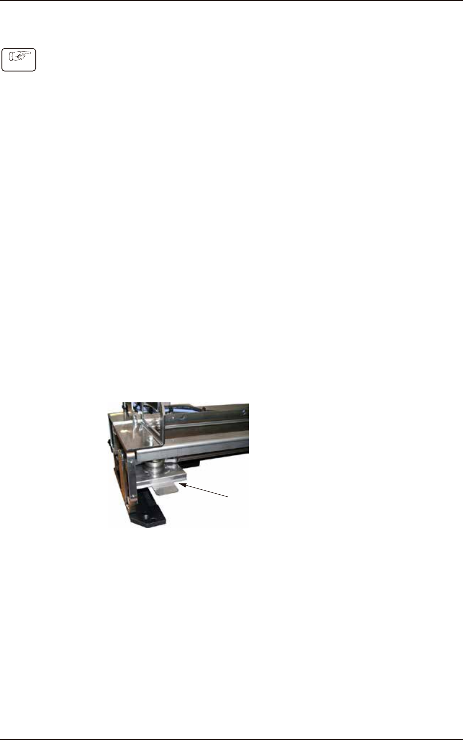
(8) Attach the cutter blade cover.
Cutter blade cover
F4B024A
Procedure
EUKYX
1-41199-4100
4.6 Cutter Section
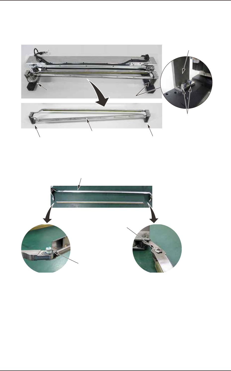
(9) Remove mounting bolts (2 each on the left and right) on the base blocks on the left and
right of the clamp lever.
Remove the clamp lever assembly with the base blocks.
When returning the base blocks to the original position, mount them with mounting bolts
after determining the position with the positioning pin.
Base block mounting bolts
Base block mounting bolts
Base block
Base block
Base block
Clamp lever assembly
F4B025
(10) Remove the connector bolts (2 each on left and right) from the base blocks of the clamp
lever. Replace with a new clamp lever.
Clamp lever (ASSY_CLAMPER_Y)
Connector bolt
Connector bolt
F4B026