EUKYX-199-4110_G5S2_Instruction_Vol4_E.pdf - 第90页
EUKYX 1-41 199-4100 4.6 Cutter Section (9 ) Remove mounting bo lts (2 each o n the lef t and right) on t he base bl ocks on t he lef t and right of the cl amp lever . Remove the clamp l ever assembl y with the ba se bloc…
EUKYX
1-40199-4100
4.6 Cutter Section
Replacing clamp lever
Cycle: 1 year (Required Time : 60 minutes)
(1) Remove the cutter unit from the main unit.
Refer to “4.6.2 Cutter Unit Lubrication” for the procedure.
(2) Remove the upper slope from the cutter unit.
Refer to “4.6.2 Cutter Unit Lubrication” for the procedure.
(3) Remove the rear cover.
Refer to “4.6.2 Cutter Unit Lubrication” or the procedure.
(4) Remove 5 hex socket head cap screws mounting the fluorine sheet assembly from the cutter
unit. Remove the fluorine sheet assembly.
Refer to “Replacing fluorine sheet” in “4.6.3 Parts replacement of the cutter unit” for the
procedure.
(5) Remove 2 truss head screws mounting the polycarbonate plate and the cable.
Remove the polycarbonate plate.
Refer to “Replacing flat ring” in “4.6.3 Parts replacement of the cutter unit” for the
procedure.
(6) Remove the hex socket head cap screws (3 each on left and right) mounting the side
brackets and the plates.
Remove the side brackets and the plates.
Refer to "Replacing flat ring" in “4.6.3 Parts replacement of the cutter unit” for the
procedure.
(7) Remove the hex socket head cap screws (2 each on left and right) mounting the frame
brackets. Remove frame brackets and the plates.
Refer to "Replacing flat ring" in “4.6.3 Parts replacement of the cutter unit” for the
procedure.
(8) Attach the cutter blade cover.
Cutter blade cover
F4B024A
Procedure
EUKYX
1-41199-4100
4.6 Cutter Section
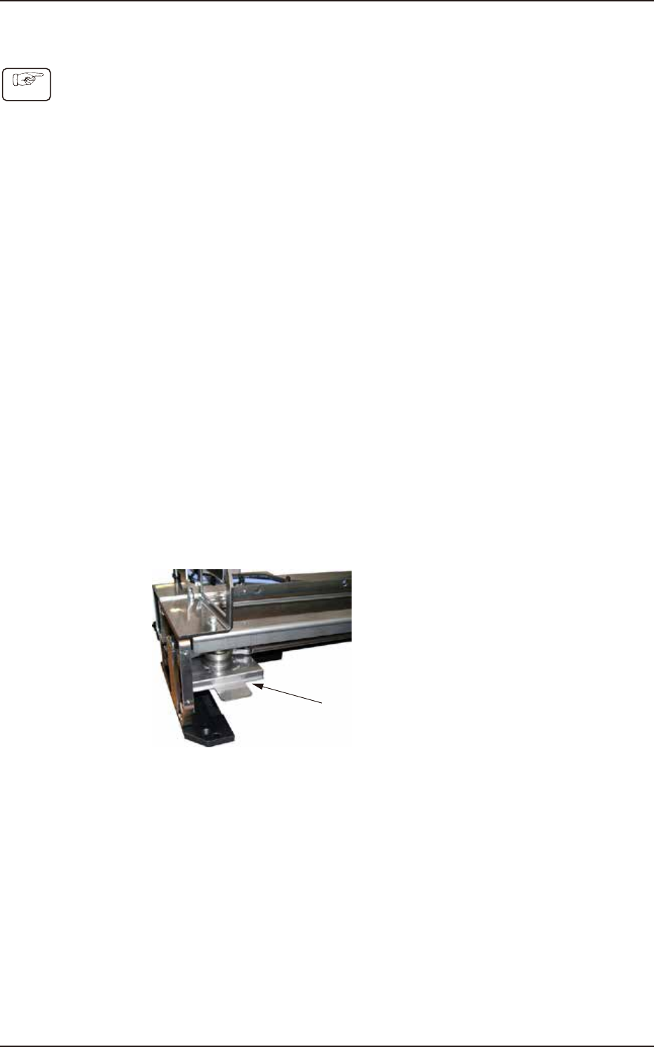
(9) Remove mounting bolts (2 each on the left and right) on the base blocks on the left and
right of the clamp lever.
Remove the clamp lever assembly with the base blocks.
When returning the base blocks to the original position, mount them with mounting bolts
after determining the position with the positioning pin.
Base block mounting bolts
Base block mounting bolts
Base block
Base block
Base block
Clamp lever assembly
F4B025
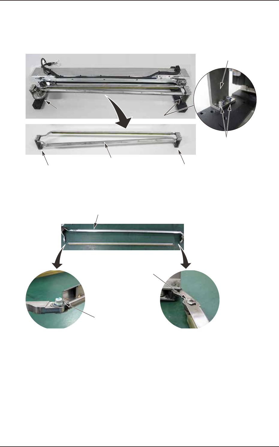
(10) Remove the connector bolts (2 each on left and right) from the base blocks of the clamp
lever. Replace with a new clamp lever.
Clamp lever (ASSY_CLAMPER_Y)
Connector bolt
Connector bolt
F4B026
EUKYX
1-42199-4100
4.7 Head Section
4.7 Head Section
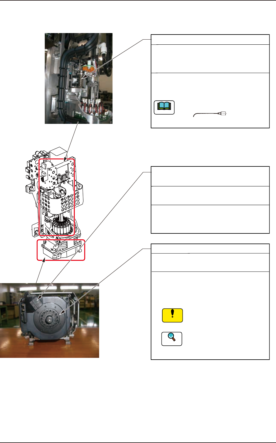
High-Speed Flexible Head
Side View Camera
(Light Emitter and Receiver)
Every Day Cleaning
Required Time: 5 minutes
When any sebum or oil is adhered to the side
view camera, rub off the dirt with a cotton
swab dipped in dehydrated ethanol.
Nozzle U/D Ball Screw (NL-Axis)
Every 3 Months Cleaning and Lubrication
(DAPHNE EPONEX GREASE No. 1)
Required Time: 5 minutes
Use No. 19 (brown) nozzle.
Note
No. 19
Wipe off the old grease with a rag and apply a
small amount of new grease to the groove of
the ball screw with a syringe.
Notice
Diffusion Plate
Every Month Cleaning
Required Time: 2 minutes
(1) Store all nozzles in the nozzle stocker
(housing) through window navigations.
(2)
Sebum or oil should not
adhere to the surface of the
diffusion plate.
Refer to "5. Nozzle Change
Window" in "Chapter 6 (Vol. 2)"
for the procedure of nozzle storage.
Reference
Wipe the diffusion plate with a dry lens
cleaning cloth.
F4A30A