Specification-SIPLACE-S25HM-eng - 第12页
10 Description A nozzle changer corresponding to the Collect & Pla ce Head in u se can be installed to the left of the PCB conve yor with no loss of feeder capacity. It will cha nge the nozzle set-up of the placement…
9
Description
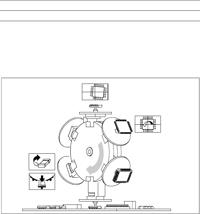
The 6-Nozzle placement head
operates on the Collect & Place
principle.
The cycle time of the 6-Nozzle
Collect & Place Head – and thus
the real achievable performance
– depends on the dimensions and
the number of leads / bumps of
the component.
Mechanically and electrically, the
6-Nozzle Collect & Place Head is
structurally very similar to the 12-
Nozzle Collect & Place Head.
Placement Heads:
6-Nozzle Collect & Place Head for High-Speed
Large Component Placement
6-Nozzle Collect & Place Head for High Speed Placement of
large components
Optical
Centering
Component
Turning
Component
Rejection
Segment
Removal Point
Technical Data
Stroke of Z-axis max. 16 mm
Programmable placement force 2.4 to 5.0 N
10
Description
A nozzle changer corresponding to
the Collect & Place Head in use
can be installed to the left of the
PCB conveyor with no loss of
feeder capacity. It will change the
nozzle set-up of the placement
head quickly and reliably for the
specific nozzle configuration valid
to a job. Damaged or faulty nozzles
can be exchanged via the menu
function on the station computer.
Placement Heads:
Nozzle Changer
Technical Data
12-Nozzle Collect & Place Head
Type of nozzle All standard nozzles of nozzle series 7xx/9xx
(special nozzles must be tested individually)
Capacity 8 magazines, each with 12 nozzles of one
nozzle type
Nozzle changing times About 2 s per nozzle
6-Nozzle Collect & Place Head
Type of nozzle All standard nozzles of nozzle series 7xx and 8xx
(special nozzles must be tested individually)
Capacity 5 magazines, each with 6 nozzles of one nozzle
series
Nozzle changing times About 2 s per nozzle
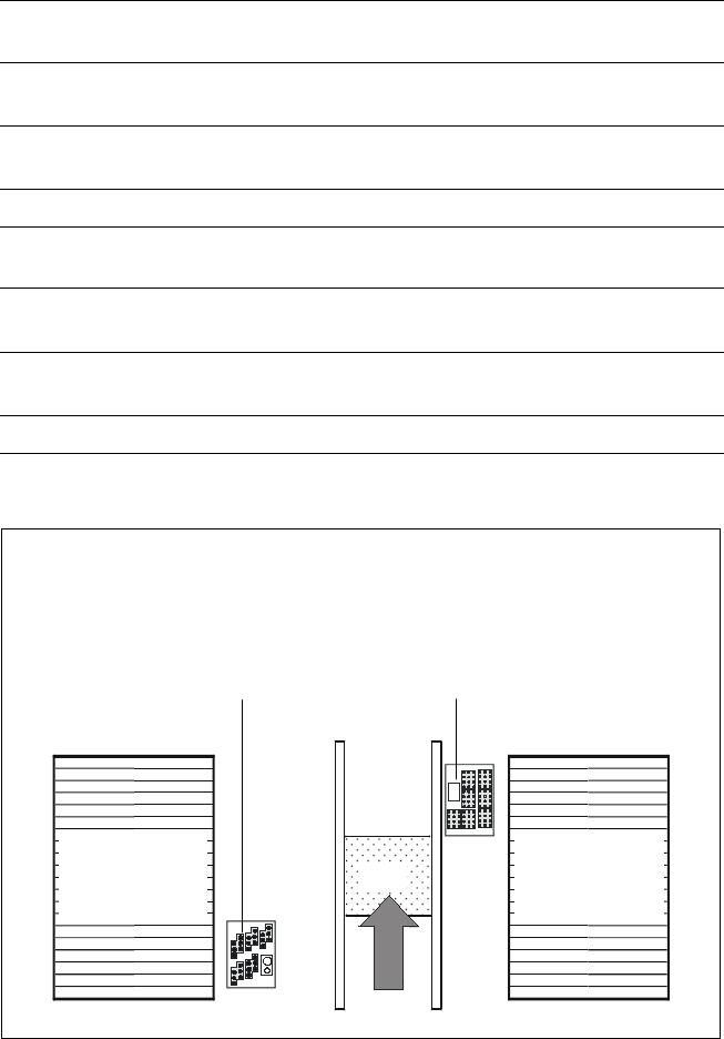
Position of Nozzle Changers
Component
Feeders for
Collect & Place
Heads
PCB
Nozzle Changer for 12-Nozzle Collect & Place Head
(7 Magazines, each with 12 Nozzles, Option)
and/or
Nozzle Changer for 6-Nozzle Collect & Place Head
(5 Magazines, each with 6 Nozzles, Option)
Component
Feeders for
Collect & Place
Heads
11
Description
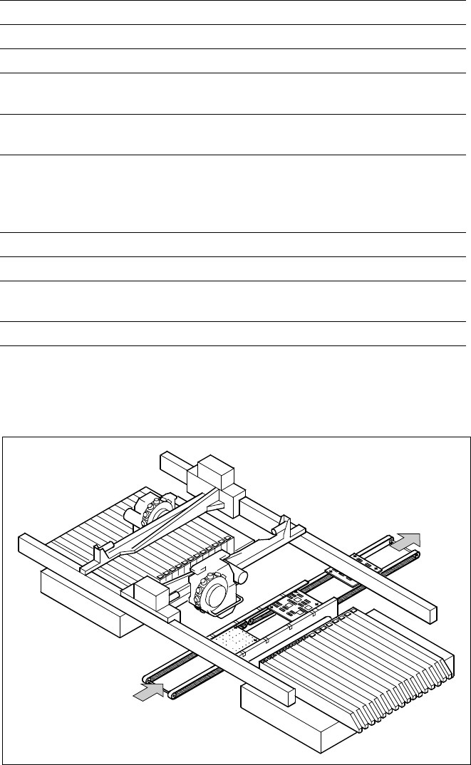
On SIPLACE S-25 HM the in-line
conveyor system guarantees a
quick adjustment to new PCB
widths. The change is made either
at the station computer using the
menu function or from the line
computer via the automatic width
adjustment unit.
Ceramic substrates can be also
transported and, if necessary, fas-
tened in place with the optional
ceramic substrate centering unit.
The conveyor can be ordered with
a fixed rail on right or left. As stan-
dard the SIPLACE placement sys-
tems are available with a single
conveyor system.
PCB Conveyor:
Single Conveyor
Technical Data
PCB dimensions See table on page 3
PCB thickness 0.5 to 4.5 mm
Max. PCB weight 3 kg
Max. PCB warpage Top: 4.5 mm - PCB thickness
Bottom: 0.5 mm + PCB thickness
Free space on PCB bottom side Standard: 25 mm,
Option: max. 40 mm
PCB conveyor height
830
± 15 mm (Standard)
900
± 15 mm (Option)
930
± 15 mm (Option)
950
± 15 mm (Option) SMEMA
Fixed conveyor edge Right (standard), left (option)
Type of interface Siemens (standard); SMEMA (option)
Component-free PCB
handling edge 3 mm
PCB loading time 2.5 s
PCB Conveyor
PCB
Transport Direction