Specification-SIPLACE-S25HM-eng - 第14页
12 Description Thanks to reduced non-productive times the dual PC B conveyor can substantially increase the through- put, depending on the progr am. It makes it possi ble to transport two PCBs through the machin e. In th…
11
Description
On SIPLACE S-25 HM the in-line
conveyor system guarantees a
quick adjustment to new PCB
widths. The change is made either
at the station computer using the
menu function or from the line
computer via the automatic width
adjustment unit.
Ceramic substrates can be also
transported and, if necessary, fas-
tened in place with the optional
ceramic substrate centering unit.
The conveyor can be ordered with
a fixed rail on right or left. As stan-
dard the SIPLACE placement sys-
tems are available with a single
conveyor system.
PCB Conveyor:
Single Conveyor
Technical Data
PCB dimensions See table on page 3
PCB thickness 0.5 to 4.5 mm
Max. PCB weight 3 kg
Max. PCB warpage Top: 4.5 mm - PCB thickness
Bottom: 0.5 mm + PCB thickness
Free space on PCB bottom side Standard: 25 mm,
Option: max. 40 mm
PCB conveyor height
830
± 15 mm (Standard)
900
± 15 mm (Option)
930
± 15 mm (Option)
950
± 15 mm (Option) SMEMA
Fixed conveyor edge Right (standard), left (option)
Type of interface Siemens (standard); SMEMA (option)
Component-free PCB
handling edge 3 mm
PCB loading time 2.5 s
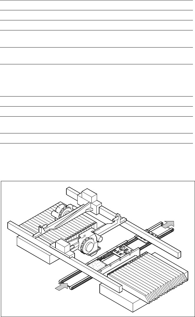
PCB Conveyor
PCB
Transport Direction
12
Description
Thanks to reduced non-productive
times the dual PCB conveyor can
substantially increase the through-
put, depending on the program. It
makes it possible to transport two
PCBs through the machine.
In the asynchronous mode of
transport a PCB is moved into the
machine in “slack time” while an-
other of the same PCB is being
populated. The non-productive
time caused by the PCB transport
is therefore completely eliminated.
The increase in placement speed
to be anticipated is between 10
and 30%, depending on the com-
ponents placed on the PCB.
PCB Conveyor:
Dual Conveyor
Technical Data
PCB dimensions See table on page 3
Fixed conveyor edge Right (standard), left (option)
Asynchronous and Synchronous Transport on Dual Conveyor
Transport mode Asynchronous Synchronous
View
Placement program
per conveyor
same or different same or different
PCB width
per conveyor
same same or different
Ink spot recognition possible not possible
Automatic width adjustment possible not possible
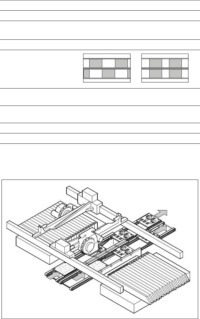
Dual Conveyor with Asynchronous Transport
PCB Transport
Direction

13
PCB
Axle
Conveyor
belt
Clamp
Description
S-25 HM (Type 2) features a new
technique for conveyors. The PCB
is clamped from the bottom to the
top side of the conveyor. This of-
fers several advantages:
§ Higher real placement rate
§ Better PCB recognition (camera
focus point)
§ Shorter PCB change time
§ Easier change of fixed conveyor
edge right/left also in field
§ Quicker learning function, as the
PCB height does not effect the
Z-stroke
The conveyor can be ordered with
a fixed rail on right or left. As stan-
dard the SIPLACE placement sys-
tems are available with a single
conveyor system.
The dual conveyor has another
advantage: It is already prepared
for a retrofit to Flexible Dual
Conveyor mode, which allows the
handling of PCBs with a maximum
width of up to 380 mm. For this
feature SW 505 is required, which
will be available at the beginning
of 2004.
PCB Conveyor:
Single and Dual Conveyor for S-25 HM (Type 2)
Technical Data
Single conveyor See table on page 11
Dual conveyor See table on page 12
Clamping of PCB
Flexible Dual Conveyor
Modus 2: Single Conveyor
Modus 1: Dual Conve
y
or