Specification-SIPLACE-S25HM-eng - 第21页
19 Description Some local safety requirements dictate that all feeder l ocations must be equipped with feeder s. If the feeder set-up does not fill all feeder locations, guards ma y be used in place of the modules. SAFET…
18
Description
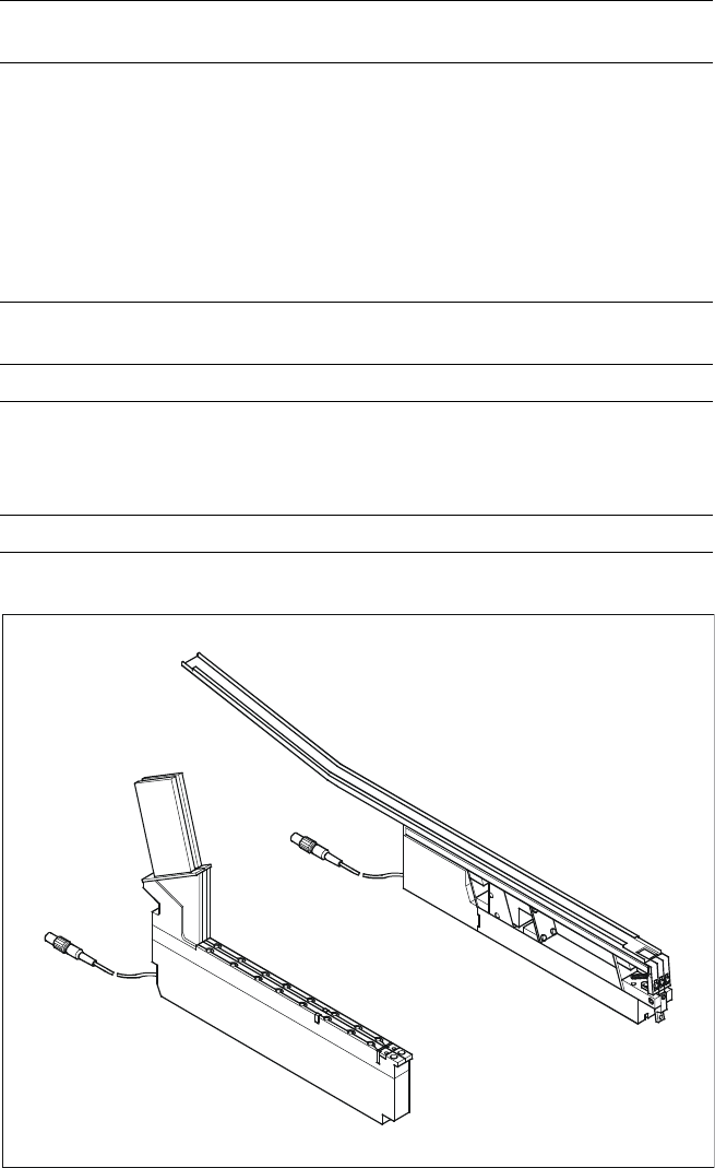
The SIPLACE Bulk Case feeder
with 2 tracks is used to handle
components packaged in standard
bulk containers. It transports rec-
tangular and cylindrical passive
components to the pick up area of
the machine. To replenish the
supply, the Bulk Cases are re-
moved and replaced outside the
machine eliminating stoppages for
replenishment.
Essentially, this feeder module
consists of a base which holds 2
feeder rails. The components are
separated and transported through
the feeder rail via compressed air.
The principle of stationary compo-
nent tables has been tried and
tested specifically with Bulk Case
components. Vibrations, which
developed when other placement
methods are used may cause
wear to the components compro-
mising quality and reliability of the
components.
The stationary component table
also brings decisive advantages for
stick magazines. The general pur-
pose vibratory stick feeder can be
refilled during the placement proc-
ess.
The feeders can be used in other
SIPLACE machines as well.
Component Supply:
Bulk Case Feeder
Stick Magazine Feeder
Technical Data
Bulk Case feeder
a
Type of packaging
Bulk Case
Feeder rails for Chip 0402 component height 0.35 mm
Chip 0402 component height 0.50 mm
Chip 0603 component height 0.45 mm
Chip 0603 component height 0.80 mm
Chip 0805 component height 0.45 mm
Chip 0805 component height 0.60 mm
Chip 0805 component height 0.85 mm
Chip 0805 component height 1.25 mm
Mini-Melf
Feeder location 1 feeder location for 2 different
component types
Stick magazine feeder Type III With control electronics
Number and width of tracks 3 x 9.5 mm
2 x 15 mm
1 x > 15 mm
1 x 30 mm
Feeder location 1
a)
Fiducial to recognize position of feeder.
Bulk Case Feeder and Stick Feeders
Bulk Case Feeder
Stick Feeder
Type III
19
Description
Some local safety requirements
dictate that all feeder locations
must be equipped with feeders.
If the feeder set-up does not fill all
feeder locations, guards may be
used in place of the modules.
SAFETY
WARNING
Component Supply:
Guard for Feeder Locations
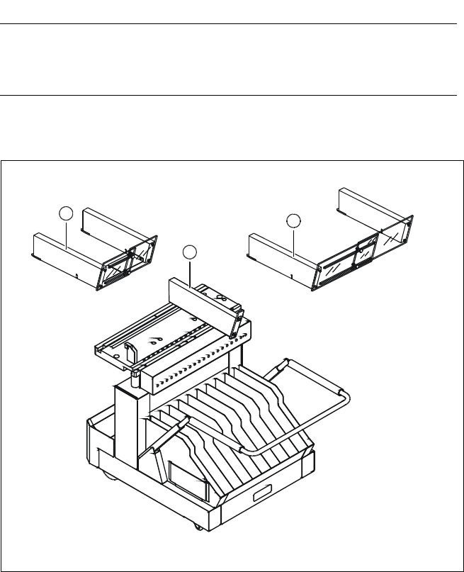
The following guard-variants can be used:
1 SIPLACE guard for 1 location
2 SIPLACE guard for 6 - 10 locations
3 SIPLACE guard for 11 - 20 locations
Various Guards for Feeder Locations
3
2
1

20
Description
For high-volume production envi-
ronments requiring a wide range
of components, the use of a
SIPLACE Matrix Tray Changer is
highly recommended. The Matrix
Tray Changer is a high-speed, high-
capacity component delivery sys-
tem for SIPLACE S-25 HM.
The SIPLACE S-25 HM can be
equipped with up to two Matrix
Tray Changers, one on each side.
When high-volume production re-
quirements include larger or tray-
type components, the SIPLACE
MTC is the best solution.
Technology
TechnologyTechnology
Technology
§ Two independent tray carriers,
each with a JEDEC tray capacity
§ Each tray carrier is equipped
with a separate drive system
§ Set-up of the MTC is carried out
in accordance with the existing
SIPLACE optimization routine
§ The carrier is moved to the level
of the tray to be accessed, then
the tray is moved precisely to
the access area for pick-up by
the placement head
§ A separate control unit is con-
nected via interface cable
§ Operator information is available
via SIPLACE station computer
§ Easy handling due to removable
waffle pack carriers
§ Large storage capacity and
multiple component set-up
possibilities
§ When a waffle pack tray is de-
pleted, an alternate tray can be
accessed
§ Quick changeover of waffle
pack tray magazines containing
up to 10 waffle pack trays
§ External set-up is possible
Component Supply:
Matrix Tray Changer (Option)
Technical Data
Dimensions (L x W x H)
of Matrix Tray Changer (MTC)
of cassette
of Waffle Pack Tray Carrier (WPTC)
of JEDEC tray
1,350 mm x 775 mm x 1,499 mm
354.1 mm x 154.8 mm x 131 mm
371 mm x 146 mm x 410.1 mm
320 mm x 135 mm
Stroke vertical (between
WPTC 1 and WPTC 40)
502.5 mm
Stroke horizontal (between
reference and component position)
approx. 640 mm
Spacing between levels 11 mm
Spacing between cassettes 134.5 mm
Storage capacity 80 WPTCs
Changeover time (over 5 levels) < 2 s
Weight of MTC
basic configuration
partially equipped
fully equipped
500 kg incl. cassettes and WPTCs
approx. 532 kg incl. components
600 kg incl. tapes and feeders
Weight of moving mass (equipped) 43.5 kg per tower
Weight of cassette approx.7.5 kg
Max. floor load fully equipped
per foot
per castor
2.78 kg/cm
2
4.01 kg/cm
2
Min. component size (L x W) 5 mm x 5 mm
Max. component height 13.5 mm
a
Max. noise generation
80 dB
A
a) When using components higher than 7.62 mm only every other tray can be used.
Electrical Connection (separate from machine power connection)
Frequency 50 Hz / 60 Hz
Phases 1; 3
Voltage 230/400 V or 110/208 V (USA)
Rated current 2.7 A or 4.2 A (USA)
Fusing 3 x 16 A
Rated current at max. load 2 A