Specification-SIPLACE-S25HM-eng - 第22页
20 Description For high-volume production en vi- ronments requiring a wid e range of components, the use of a SIPLAC E Matrix Tray C hanger is highly recommended. The M atrix Tray Changer i s a high- speed, high- capacit…
19
Description
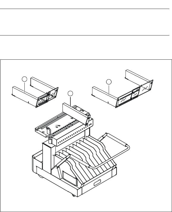
Some local safety requirements
dictate that all feeder locations
must be equipped with feeders.
If the feeder set-up does not fill all
feeder locations, guards may be
used in place of the modules.
SAFETY
WARNING
Component Supply:
Guard for Feeder Locations
The following guard-variants can be used:
1 SIPLACE guard for 1 location
2 SIPLACE guard for 6 - 10 locations
3 SIPLACE guard for 11 - 20 locations
Various Guards for Feeder Locations
3
2
1

20
Description
For high-volume production envi-
ronments requiring a wide range
of components, the use of a
SIPLACE Matrix Tray Changer is
highly recommended. The Matrix
Tray Changer is a high-speed, high-
capacity component delivery sys-
tem for SIPLACE S-25 HM.
The SIPLACE S-25 HM can be
equipped with up to two Matrix
Tray Changers, one on each side.
When high-volume production re-
quirements include larger or tray-
type components, the SIPLACE
MTC is the best solution.
Technology
TechnologyTechnology
Technology
§ Two independent tray carriers,
each with a JEDEC tray capacity
§ Each tray carrier is equipped
with a separate drive system
§ Set-up of the MTC is carried out
in accordance with the existing
SIPLACE optimization routine
§ The carrier is moved to the level
of the tray to be accessed, then
the tray is moved precisely to
the access area for pick-up by
the placement head
§ A separate control unit is con-
nected via interface cable
§ Operator information is available
via SIPLACE station computer
§ Easy handling due to removable
waffle pack carriers
§ Large storage capacity and
multiple component set-up
possibilities
§ When a waffle pack tray is de-
pleted, an alternate tray can be
accessed
§ Quick changeover of waffle
pack tray magazines containing
up to 10 waffle pack trays
§ External set-up is possible
Component Supply:
Matrix Tray Changer (Option)
Technical Data
Dimensions (L x W x H)
of Matrix Tray Changer (MTC)
of cassette
of Waffle Pack Tray Carrier (WPTC)
of JEDEC tray
1,350 mm x 775 mm x 1,499 mm
354.1 mm x 154.8 mm x 131 mm
371 mm x 146 mm x 410.1 mm
320 mm x 135 mm
Stroke vertical (between
WPTC 1 and WPTC 40)
502.5 mm
Stroke horizontal (between
reference and component position)
approx. 640 mm
Spacing between levels 11 mm
Spacing between cassettes 134.5 mm
Storage capacity 80 WPTCs
Changeover time (over 5 levels) < 2 s
Weight of MTC
basic configuration
partially equipped
fully equipped
500 kg incl. cassettes and WPTCs
approx. 532 kg incl. components
600 kg incl. tapes and feeders
Weight of moving mass (equipped) 43.5 kg per tower
Weight of cassette approx.7.5 kg
Max. floor load fully equipped
per foot
per castor
2.78 kg/cm
2
4.01 kg/cm
2
Min. component size (L x W) 5 mm x 5 mm
Max. component height 13.5 mm
a
Max. noise generation
80 dB
A
a) When using components higher than 7.62 mm only every other tray can be used.
Electrical Connection (separate from machine power connection)
Frequency 50 Hz / 60 Hz
Phases 1; 3
Voltage 230/400 V or 110/208 V (USA)
Rated current 2.7 A or 4.2 A (USA)
Fusing 3 x 16 A
Rated current at max. load 2 A

21
Technical Data
Tape size: Combi module 8 / 12 / 16 mm
Recommended Bare Die size: 8 mm Surf Tape:
1 x 1 mm
2
up to 2.3 x 2.3 mm
2
12 mm Surf Tape:
2.3 x 2.3 mm
2
up to 5 x 5 mm
2
16 mm Surf Tape:
3.8 x 3.8 mm
2
up to 9.5 x 9.5 mm
2
Component positional
requirements:
Size of Bare Die
≤ 2.3 x 2.3 mm
2
:
± 100 µm / 6 σ
Size of Bare Die ≥ 2.3 x 2.3 mm
2
:
± 200 µm / 6 σ
(in relation to center of pocket)
Min. space between tape pocket
web and edge of die: 0.4 mm (0.015 mil)
Tape specification: IEC 286-3, DIN-IEC-286, EIA 481 und
JIS C 0806
Tape reel diameter: 7" or 15" (178 or 381 mm)
Feeder space 1 slot
Description
The Surf Tape feeder is a specific
module for the placement of Bare
Dies. The feeding technology is
different from a standard feeder
and requires a poke-up to remove
the component from the carrier.
The Surf Tape feeder is offered as
a combination module for 8 / 12 /
16 mm Surf Tape material. To
switch from one tape size to the
other is done very easily by
changing only three parts that are
included with the feeder.
The feeding process starts with
the transport of the Bare Die to
the pick up position. A sensor ex-
actly defines this position. The
nozzle moves onto the Bare Die
and the vacuum is activated. A
poke-up needle moves up and lifts
up the Bare Die and the nozzle. At
the same time the Surf Tape starts
to loose contact with the Bare Die.
When there is no contact between
the tape and the Bare Die the noz-
zle moves up and the poke-up
needle moves down. The required
time for this process depends on
different items like storage time of
the tape, size of the Bare Die etc.
and is adjustable.
For the assembly of Bare Dies
please refer also to:
§ Surf Tape Feeder
§ DCA-Vision
Component Supply:
Surf Tape Feeder for Bare Dies