Specification-SIPLACE-S25HM-eng - 第24页
22 Description The bar code scanner enables a quick and reliab le check of com- ponent set-up and refill. The bar codes of the tracks and the lo aded components assigned to the track s (bar code labe ls on tap es, Bulk C…

21
Technical Data
Tape size: Combi module 8 / 12 / 16 mm
Recommended Bare Die size: 8 mm Surf Tape:
1 x 1 mm
2
up to 2.3 x 2.3 mm
2
12 mm Surf Tape:
2.3 x 2.3 mm
2
up to 5 x 5 mm
2
16 mm Surf Tape:
3.8 x 3.8 mm
2
up to 9.5 x 9.5 mm
2
Component positional
requirements:
Size of Bare Die
≤ 2.3 x 2.3 mm
2
:
± 100 µm / 6 σ
Size of Bare Die ≥ 2.3 x 2.3 mm
2
:
± 200 µm / 6 σ
(in relation to center of pocket)
Min. space between tape pocket
web and edge of die: 0.4 mm (0.015 mil)
Tape specification: IEC 286-3, DIN-IEC-286, EIA 481 und
JIS C 0806
Tape reel diameter: 7" or 15" (178 or 381 mm)
Feeder space 1 slot
Description
The Surf Tape feeder is a specific
module for the placement of Bare
Dies. The feeding technology is
different from a standard feeder
and requires a poke-up to remove
the component from the carrier.
The Surf Tape feeder is offered as
a combination module for 8 / 12 /
16 mm Surf Tape material. To
switch from one tape size to the
other is done very easily by
changing only three parts that are
included with the feeder.
The feeding process starts with
the transport of the Bare Die to
the pick up position. A sensor ex-
actly defines this position. The
nozzle moves onto the Bare Die
and the vacuum is activated. A
poke-up needle moves up and lifts
up the Bare Die and the nozzle. At
the same time the Surf Tape starts
to loose contact with the Bare Die.
When there is no contact between
the tape and the Bare Die the noz-
zle moves up and the poke-up
needle moves down. The required
time for this process depends on
different items like storage time of
the tape, size of the Bare Die etc.
and is adjustable.
For the assembly of Bare Dies
please refer also to:
§ Surf Tape Feeder
§ DCA-Vision
Component Supply:
Surf Tape Feeder for Bare Dies
22
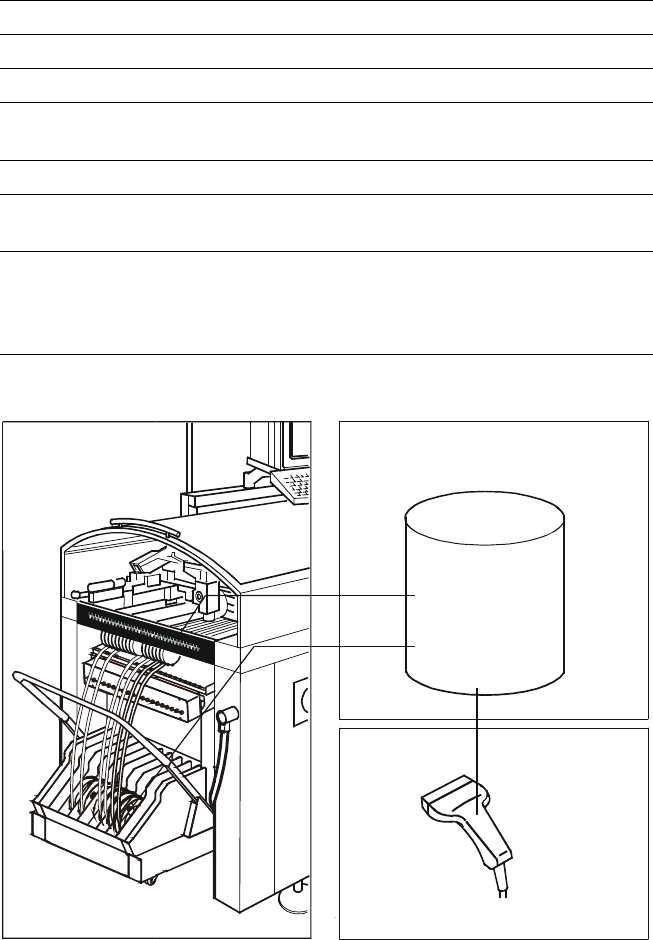
Description
The bar code scanner enables a
quick and reliable check of com-
ponent set-up and refill. The bar
codes of the tracks and the loaded
components assigned to the
tracks (bar code labels on tapes,
Bulk Cases, etc.) are read in with a
hand scanner. An audible and opti-
cal signal acknowledges a suc-
cessful reading operation. If the la-
bel is damaged the bar code can
be entered at the keyboard.
The allocation of the components
to their respective track is de-
scribed in the set-up data. An error
message is displayed if the data
received from the bar code scan-
ner does not conform to the set-up
data.
If the set-up check is switched on,
it becomes a mandatory step in
the set-up process. If it is
switched off the set-up check is
optional.
Component Supply:
Component Bar Code Scanner for Set-Up and Refill Check
(Option)
Technical Data
Connection Station computer
Data input Bar code scanner or keyboard
Number of characters Max. 40
Restrictions Bar codes beginning with number 1 or 2
and with less than 5 characters
Number of bar codes Max. 6 per component
Number of filters
to extract relevant data Max. 1 per bar code
Preset code types Code 39 (standard or full ASCII),
Code 2 from 5 interleaved and normal,
Code 128, UPC/EAN/JAN codes
(more on request)
Component
Control
Set-Up File
Track Bar Code
Component
Bar Code
Scanner
The scanner checks the corresponding track and
the components
23
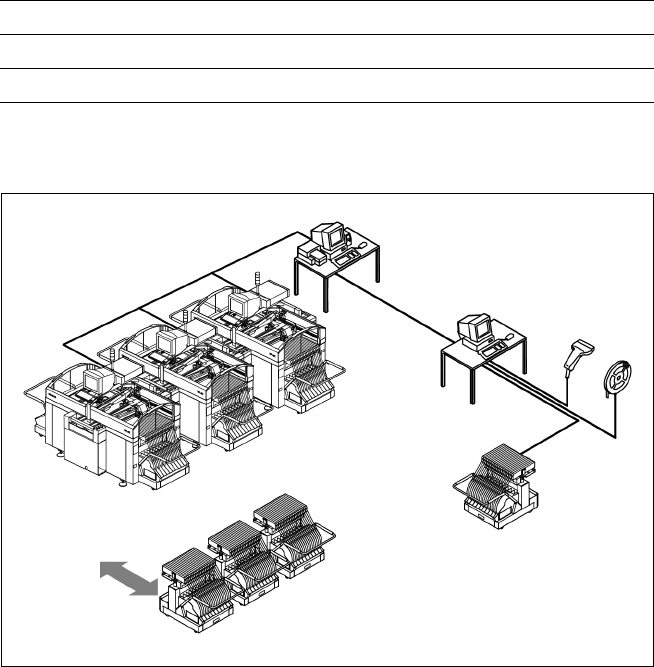
Description
The component changeover tables
can be set up and checked at an
external SIPLACE set-up station
quickly and without machine idle
time. The costs for production in-
volving a wide variety of compo-
nents are greatly reduced. During
the bar code check outside the
machine, 10 minutes of machine
standstill are eliminated per set-up
change. All current data from up to
4 lines are accessible over a link to
the line computer via a Local Area
Network (LAN).
In the case of the SIPLACE S-25
HM a component changeover ta-
ble is part of the standard equip-
ment. Additional changeover ta-
bles are required for optimal use
of the set-up station.
Component Supply:
SIPLACE External Set-Up Station (Option)
Technical Data
Operating system Windows NT 4.0
Set-up check Per bar code scanner
Component table change Time expanded: 2 min / table side
Example for SIPLACE Set-Up Station
Line
LAN
Line Computer
PC for External set-up
LAN Scanner
Serial Interface
Tape Reel
with
Bar Code
Mobile
Changeover
Table
Mobile
Changeover
Tables