Specification-SIPLACE-S25HM-eng - 第3页
1 Subject to change without notice. Edition 3 1202-S-25- 600-e Order No E80002-P10 4-A409-X -7600 This sp ecificat ion is va lid both f or SIPLACE S-25 HM (standard) and SIPLACE S-25 HM (2 ) (= machine label). In case of…
1
Subject to change
without notice.
Edition 3
1202-S-25-600-e
Order No
E80002-P104-A409-X-7600
This specification is valid both for
SIPLACE S-25 HM (standard) and
SIPLACE S-25 HM (2) (= machine
label). In case of differences tech-
nical data of SIPLACE S-25 HM (2)
are marked with “Type 2”.
Machine Description 3
Line Design 4
Placement Heads 5
Head Modularity
Placement Accuracy
Component Range
12-Nozzle Collect & Place Head for High Speed
Component Placement
6-Nozzle Collect & Place Head for High-Speed Large
Component Placement
Nozzle Changer
PCB Conveyor 11
Single Conveyor
Dual Conveyor
Ceramic Substrate Centering (Option)
PCB Bar Code for Production-Controlled Manufacturing
(Option)
Component Supply 16
Changeover Table
Tape Feeder
Bulk Case Feeder
Stick Magazine Feeder
Guard for Feeder Locations
Matrix Tray Changer (Option)
Surf Tape Feeder for Bare Dies
Component Bar Code Scanner for Set-Up and Refill Check
(Option)
SIPLACE External Set-Up Station (Option)
Vision Sensor Technology 24
PCB Vision Module
PCB Position Recognition
Bad Board Recognition
Position Recognition of Feeder
Algorithms to determine the X-/Y-Position and the Rotation
Angle of Components
Standard Component Vision Modules for 12- and 6-Nozzle
Collect & Place Head
DCA-Vision Module for 12- and 6-Nozzle Collect & Place Head
(Option)
Machine Criteria 29
Placement Accuracy
Placement Reliability
Mapping (Option)
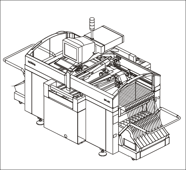
High Speed SMD Placement System
SIPLACE S-25 HM
2
SIPLACE Software Architecture 32
SIPLACE Pro
Technical Data 33
Signal Interfaces
Connections
Dimensions and Set-Up Conditions
Transporting and Commissioning
Possible Machine Configuration 38
High Speed SMD Placement System
SIPLACE S-25 HM
SIPLACE S-25 HM