Specification-SIPLACE-S25HM-eng - 第30页
28 Description Standar d Component Vision Standar d Component Vision Standar d Component Vision Standar d Component Vision Module for 12- an d 6-Noz zle Module for 12- an d 6-Noz zle Module for 12- an d 6-Noz zle Module …

27
Description
The component vision modules
perform a critical contribution to
placement accuracy and reliability.
It dependably recognizes all pack-
age forms (= geometric dimen-
sions of the component) illumi-
nated at various angles from a
number of planes. To illuminate
each component optimally, the
luminosity of the individual planes
can be adjusted individually in 256
levels.
Aside from the dimension of the
SMD component, the vision sys-
tem determines the lead number
and pitch (lateral IC lead bend) as
well as the rotation angle and X-/Y-
offset. Components which are not
suitable are rejected and automati-
cally corrected in a repair cycle.
Rotational and X-/Y-offsets are cor-
rected at the turning station of the
Collect & Place Head or via the
gantry axes. A relevant X-/Y-pick-
up offset is calculated from the
positions of a number of compo-
nents from one track. This is fac-
tored in accordance with the self-
learning principle during the sub-
sequent pick-up of components.
Prior to placement the required
geometrical dimensions of one
component type are entered into
the package form (GF) editor, cre-
ating a synthetic model of the
SMD module. This task is simpli-
fied by the comprehensive on-line
information and Help system.
Later the central SIPLACE vision
system, to which all other vision
modules are connected, analyzes
the gray-scale picture of the com-
ponent vision module. To this end,
suitable algorithms are used for
the pertinent package type. Due to
the combination of algorithms, the
vision system also functions relia-
bly under the most difficult condi-
tions, e.g., in the case of different
reflection behavior by the leads or
disruptive influences from the out-
side.
The algorithms are used for all
component vision modules.
Vision Sensor Technology:
Algorithms to determine the X-/Y-Position and the
Rotation Angle of Components
Algorithm Component Determined on the basis of
Size Driven Chip the component’s outline
(profile/gradients)
Row Driven IC several component leads
(correlation method)
Corner Driven IC all component leads
(correlation method)
Lead Driven Complex IC each component connection
(High-Accuracy-Lead-Extraction method)
Grid/Ball/Bump BGA, µBGA,
Flip Chip
all defined balls and bumps
(gradients/ball or bump centering)

28
Description
Standard Component Vision
Standard Component VisionStandard Component Vision
Standard Component Vision
Module for 12- and 6-Nozzle
Module for 12- and 6-NozzleModule for 12- and 6-Nozzle
Module for 12- and 6-Nozzle
Co
CoCo
Col
ll
llect & Place Head
lect & Place Headlect & Place Head
lect & Place Head
The standard component vision
module is directly integrated into
the Collect & Place Head. While
the component is cycling into the
next station of the Collect & Place
Head, the recorded image is
evaluated by the central vision sys-
tem. The component rotation is
then corrected by the appropriate
angle based on the position off-
sets determined with vision in-
spection.
DCA Vision Module for 12- and
DCA Vision Module for 12- andDCA Vision Module for 12- and
DCA Vision Module for 12- and
6-Nozzle Collect & Place Head
6-Nozzle Collect & Place Head6-Nozzle Collect & Place Head
6-Nozzle Collect & Place Head
The DCA vision module was de-
veloped specifically for secure,
fast and reliable recognition of Flip
Chips and Bare Dies. But also
standard SMDs can be handled
with this vision module including
0201 capacitors and resistors.
The DCA vision module option of-
fers the possibility to process with
one machine SMDs, Flip Chips and
Bare Dies without problems, thus
achieving a maximum of flexibility.
The DCA-Vision Module option re-
places the Standard Component
Vision Module.
Vision Sensor Technology:
Standard Component Vision Modules for 12- and 6-Nozzle
Collect & Place Head
DCA-Vision Module for 12- and 6-Nozzle Collect & Place Head (Option)
Standard Component Vision Module for the 12-Nozzle C & P Head
Maximum component size 18.7 x 18.7 mm
2
Component Range See table on page 6
Camera’s field of view 24 x 24 mm
2
Illumination Front lighting
(3 freely programmable planes)
Standard Component Vision Module for the 6-Nozzle C & P Head
Maximum component size 32 x 32 mm
2
Component Range See table on page 6
Camera’s field of view 39 x 39 mm
2
Illumination Front light
(2 freely programmable planes)
DCA-Vision Module for 12- and 6-Nozzle C & P Head
Component size: minimum 0.6 x 0.3 mm
2
(0201) /
maximum 13 x 13 mm
2
Component Range Flip Chips, Bare Dies, Standard SMDs
Camera’s field of view 15.6 x 15.6 mm
2
Illumination Front light
(4 freely programmable planes)
29
Description
Various factors contribute to the
placement accuracy of the
SIPLACE S-25 HM machine, e.g.,
the stationary PCB during the
placement process. As no accel-
erations are acting on the placed
components, their position contin-
ues unchanged. The PCB moves in
and out at a coordinated speed
which is automatically reduced just
before the nominal position is
reached.
A further guarantee for long-term
high placement accuracy is the
position recognition of the axes of
the gantry and placement head by
means of optical scanning by in-
cremental encoders. Revolving
star and segments of the Collect
& Place Head are positioned by
means of high-resolution glass in-
cremental panels. The X- and Y-
axes are positioned with the help
of the metal scales on each gantry
axis.
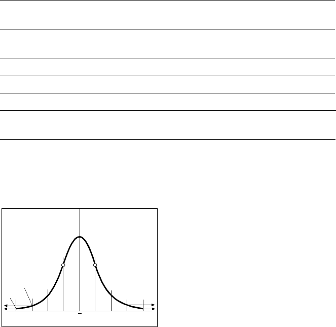
To determine the placement accu-
racy on SIPLACE machines, highly
precision glass components with
mounted structures are placed on
a dimensionally accurate glass
mapping plate. The results are sta-
tistically evaluated and presented
as a Gaussian standard distribu-
tion. In the case of the 6-Nozzle
Collect & Place Head at the
SIPLACE S-25 HM the placement
accuracy is ± 70 µm at a statistical
reliability of 4 sigma. If the accu-
racy value ± 70 µm is divided by
the sigma value 4, the result is the
standard deviation S of 1 sigma =
± 17.5 µm (as defined in “Scope
of Service and Delivery SIPLACE”).
A machine capability analysis is
conducted for each machine ac-
ceptance test.
Machine Criteria:
Placement Accuracy
Technical Data Gantry
Drive Brushless AC Temperature
Controlled Motor
Position measuring system
(X/Y)
Linear scales
Resolution of X-/Y-axis 2.5 µm
Speed of X-axis max. 2.5 m/s
Speed of Y-axis max. 2.5 m/s
Placement Accuracy see table on page 6
Standard Deviation - dpm
-4
σ
-3
σ
-2
σ
σ
x
σ
2
σ
3
σ
4
σ
2700 dpm
60 dpm
P Point o
f
In
f
lection