Specification-SIPLACE-S25HM-eng - 第31页
29 Description Various factors contribute to the placement accur acy of the SIPLACE S-25 HM machine, e.g., the stationar y PCB during the placement process. As no accel- erations are acti ng on the placed components, the…

28
Description
Standard Component Vision
Standard Component VisionStandard Component Vision
Standard Component Vision
Module for 12- and 6-Nozzle
Module for 12- and 6-NozzleModule for 12- and 6-Nozzle
Module for 12- and 6-Nozzle
Co
CoCo
Col
ll
llect & Place Head
lect & Place Headlect & Place Head
lect & Place Head
The standard component vision
module is directly integrated into
the Collect & Place Head. While
the component is cycling into the
next station of the Collect & Place
Head, the recorded image is
evaluated by the central vision sys-
tem. The component rotation is
then corrected by the appropriate
angle based on the position off-
sets determined with vision in-
spection.
DCA Vision Module for 12- and
DCA Vision Module for 12- andDCA Vision Module for 12- and
DCA Vision Module for 12- and
6-Nozzle Collect & Place Head
6-Nozzle Collect & Place Head6-Nozzle Collect & Place Head
6-Nozzle Collect & Place Head
The DCA vision module was de-
veloped specifically for secure,
fast and reliable recognition of Flip
Chips and Bare Dies. But also
standard SMDs can be handled
with this vision module including
0201 capacitors and resistors.
The DCA vision module option of-
fers the possibility to process with
one machine SMDs, Flip Chips and
Bare Dies without problems, thus
achieving a maximum of flexibility.
The DCA-Vision Module option re-
places the Standard Component
Vision Module.
Vision Sensor Technology:
Standard Component Vision Modules for 12- and 6-Nozzle
Collect & Place Head
DCA-Vision Module for 12- and 6-Nozzle Collect & Place Head (Option)
Standard Component Vision Module for the 12-Nozzle C & P Head
Maximum component size 18.7 x 18.7 mm
2
Component Range See table on page 6
Camera’s field of view 24 x 24 mm
2
Illumination Front lighting
(3 freely programmable planes)
Standard Component Vision Module for the 6-Nozzle C & P Head
Maximum component size 32 x 32 mm
2
Component Range See table on page 6
Camera’s field of view 39 x 39 mm
2
Illumination Front light
(2 freely programmable planes)
DCA-Vision Module for 12- and 6-Nozzle C & P Head
Component size: minimum 0.6 x 0.3 mm
2
(0201) /
maximum 13 x 13 mm
2
Component Range Flip Chips, Bare Dies, Standard SMDs
Camera’s field of view 15.6 x 15.6 mm
2
Illumination Front light
(4 freely programmable planes)
29
Description
Various factors contribute to the
placement accuracy of the
SIPLACE S-25 HM machine, e.g.,
the stationary PCB during the
placement process. As no accel-
erations are acting on the placed
components, their position contin-
ues unchanged. The PCB moves in
and out at a coordinated speed
which is automatically reduced just
before the nominal position is
reached.
A further guarantee for long-term
high placement accuracy is the
position recognition of the axes of
the gantry and placement head by
means of optical scanning by in-
cremental encoders. Revolving
star and segments of the Collect
& Place Head are positioned by
means of high-resolution glass in-
cremental panels. The X- and Y-
axes are positioned with the help
of the metal scales on each gantry
axis.
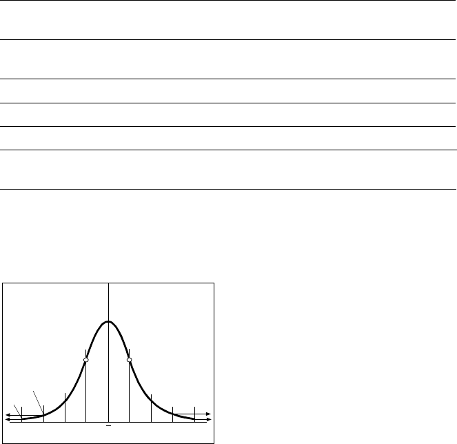
To determine the placement accu-
racy on SIPLACE machines, highly
precision glass components with
mounted structures are placed on
a dimensionally accurate glass
mapping plate. The results are sta-
tistically evaluated and presented
as a Gaussian standard distribu-
tion. In the case of the 6-Nozzle
Collect & Place Head at the
SIPLACE S-25 HM the placement
accuracy is ± 70 µm at a statistical
reliability of 4 sigma. If the accu-
racy value ± 70 µm is divided by
the sigma value 4, the result is the
standard deviation S of 1 sigma =
± 17.5 µm (as defined in “Scope
of Service and Delivery SIPLACE”).
A machine capability analysis is
conducted for each machine ac-
ceptance test.
Machine Criteria:
Placement Accuracy
Technical Data Gantry
Drive Brushless AC Temperature
Controlled Motor
Position measuring system
(X/Y)
Linear scales
Resolution of X-/Y-axis 2.5 µm
Speed of X-axis max. 2.5 m/s
Speed of Y-axis max. 2.5 m/s
Placement Accuracy see table on page 6
Standard Deviation - dpm
-4
σ
-3
σ
-2
σ
σ
x
σ
2
σ
3
σ
4
σ
2700 dpm
60 dpm
P Point o
f
In
f
lection
30
Description
In addition to correct positioning,
placement reliability is important.
On the SIPLACE S-25 HM this is
ensured through a number of con-
trol functions, such as vacuum
checks and component vision
testing during the placement se-
quence.
Out of tolerance components are
rejected, placed on the repair list
and automatically processed dur-
ing a repair cycle. An offset in the
position of the PCB relative to the
conveyor system (PCB vision) and
an offset of the X-axis, Y-axis or ro-
tation of the component relative to
the midpoint of the nozzle (com-
ponent vision) trigger an immedi-
ate correction to ensure placement
accuracy.
Since the PCB is fixed, the com-
ponents remain in the exact posi-
tion they are placed. The stationary
component table ensures a pre-
cise pick up. Options, such as the
component bar code scanner, can
be added to further enhance reli-
ability.
Placement errors
Placement errorsPlacement errors
Placement errors
Errors that occur after the compo-
nent has been placed on the PCB.
They include:
§ Component is missed on PCB
§ Too many components on PCB
§ Components not placed prop-
erly on PCB
§ Components placed while
standing on edge
Machine Criteria:
Placement Reliability
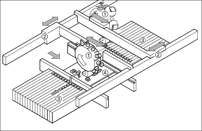
Placement Principle of SIPLACE S-25
HM
➀ 6-Nozzle or 12-Nozzle
Collect & Place Head
➁ X-/Y-Gantry System
➂ Fixed Component Supply
➃ Fixed PCB