Specification-SIPLACE-S25HM-eng - 第35页
33 1. After switching-on the station Technical Data: Signal Interfaces Signal Interface (20-Pin Ribbon C able Connector) to upstream station x3 to down stream station x4 Pin 13 GND 24 V Pin 10 R eserved Pin 14 Arrived Pi…
32
Description
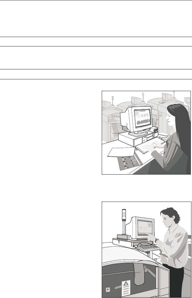
SIPLACE Pro is the programming
software for all SIPLACE place-
ment machines and placement
lines. It is designed to support the
stand alone capability, Siemens
line configuration and the seam-
less integration into a CIM envi-
ronment.
SIPLACE Pro is a client/server
software system that delivers out-
standing PCB programming per-
formance. It consists of the
SIPLACE Pro Server and Database
for centralized storing of all placing
programs in use and the SIPLACE
Pro Desk to assist all day to day in-
teractions with SIPLACE place-
ment machines.
SIPLACE Pro runs on standard
hardware (PC). It is based on Win-
dows NT with tree controls, drag
and drop as well as all standard
Windows NT features.
It works directly on the placement
system itself for operator interac-
tion, or any PC – standing alone or
connected to the LAN of the
SIPLACE line. SIPLACE Pro has
features for monitoring, program-
ming, line balancing and set-up
optimization. Thus a separate line
computer is no longer necessary.
But for offline programming the
SIPLACE Pro software can be run
on a separate standard PC as well.
With its powerful and enhanced
graphical user interface SIPLACE
Pro offers programmers and day
to day users
For more detailed information
please see “SIPLACE Software
Specification”.
SIPLACE Software Architecture:
SIPLACE Pro
Functions
SIPLACE Pro Server and
Database
Data Preparation
Optimization
Line control
Line monitoring
Data management
Softwareversion SIPLACE Pro 1.3
SIPLACE Pro Desk
Machine control
Machine monitoring
Machine operation
Softwareversion From 503.xx
SIPLACE Pro Server and
Database
SIPLACE Pro Desk
33
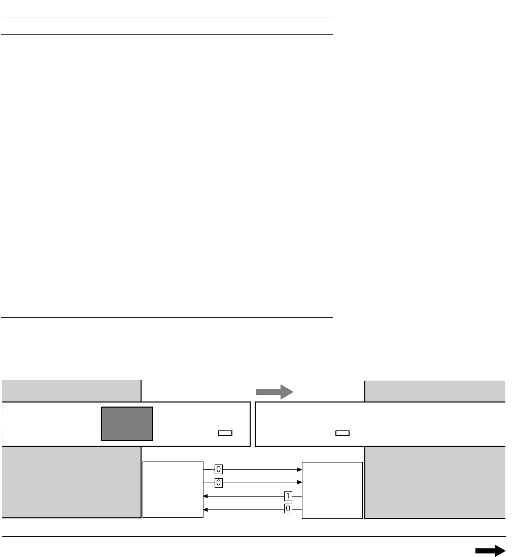
1. After switching-on the station
Technical Data:
Signal Interfaces
Signal Interface (20-Pin Ribbon Cable Connector)
to upstream station x3 to downstream station x4
Pin 13 GND 24 V Pin 10 Reserved
Pin 14 Arrived Pin 9 Reserved
Pin 15 Permission Pin 8 Reserved
Pin 19 Request Pin 4 +30 V DC
unsaturated
Pin 20 GND 24 V for request / re-
leased (contact separation)
Pin 5 GND 24 V
Pin 18 Released Pin 6 +24 V DC
Pin 12 Trouble signal loop Pin 11 Trouble signal loop
Pin 11 Pin 12
Pin 3 +24 V DC Pin 15 Permission
Pin 2 GND 24 V Pin 13 GND 24 V for per-
mission / arrived
(contact separation)
Pin 1 +30 V DC unsaturated Pin 14 Arrived
Pin 8 Reserved Pin 18 Released
Pin 9 Reserved Pin 19 Released
Pin 10 Reserved Pin 20 GND 24 V
Requirement
Delivery
Permission
Receival
Requirement
Delivery
Permission
Receival
Transport Direction
Conveyor Section 1
PCB
Sensor
PCB
Sensor
Conveyor Section 2
Station n
transports
PCB
to delivery
Station n+1
is ready to
receive PCBs
Conveyor 1 is On Conveyor 2 is Off
34
Technical Data:
Signal Interfaces
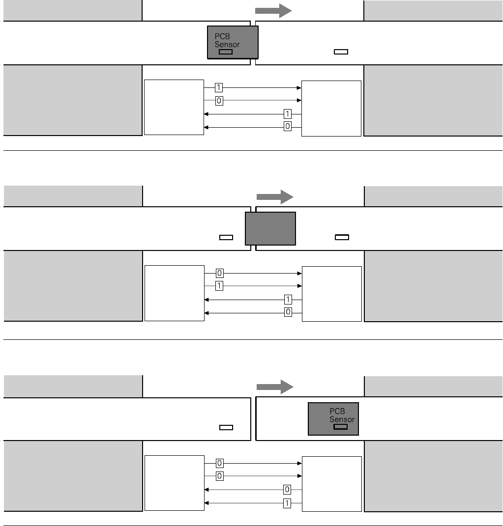
2. PCB handling has started
Conveyor 1 is On Conveyor 2 is On
Transport Direction
Conveyor Section 1
Conveyor Section 2
Station n
delivers PCB
to station n+1
Station n+1
waits for PCB
from station n
Requirement
Delivery
Permission
Receival
Requirement
Delivery
Permission
Receival
PCB
Sensor
Transport Direction
Conveyor Section 1
PCB
Sensor
Conveyor Section 2
Station n
has just
delivered PCB
Station n+1
waits for PCB from
station n, but has
not received it
Requirement
Delivery
Permission
Receival
Requirement
Delivery
Permission
Receival
PCB
Sensor
3. PCB is at delivery
Conveyor 1 is Off Conveyor 2 is On
Conveyor 1 is Off Conveyor 2 is On
Transport Direction
Conveyor Section 1
PCB
Sensor
Conveyor Section 2
Station n Station n+1
has just received
the PCB
Requirement
Delivery
Permission
Receival
Requirement
Delivery
Permission
Receival
4. PCB transport is finished
A detailed documentation of the
PCB transport signal interface is
available on request.