Specification-SIPLACE-S25HM-eng - 第4页
2 SIPLACE So ftware Archit ecture 32 SIPLACE Pro Technical Data 33 Signal In terfaces Connection s Dimension s and Set-Up Condition s Transporting and Commi ssioning Possible Mac hine Configuration 38 High Speed SMD Plac…
1
Subject to change
without notice.
Edition 3
1202-S-25-600-e
Order No
E80002-P104-A409-X-7600
This specification is valid both for
SIPLACE S-25 HM (standard) and
SIPLACE S-25 HM (2) (= machine
label). In case of differences tech-
nical data of SIPLACE S-25 HM (2)
are marked with “Type 2”.
Machine Description 3
Line Design 4
Placement Heads 5
Head Modularity
Placement Accuracy
Component Range
12-Nozzle Collect & Place Head for High Speed
Component Placement
6-Nozzle Collect & Place Head for High-Speed Large
Component Placement
Nozzle Changer
PCB Conveyor 11
Single Conveyor
Dual Conveyor
Ceramic Substrate Centering (Option)
PCB Bar Code for Production-Controlled Manufacturing
(Option)
Component Supply 16
Changeover Table
Tape Feeder
Bulk Case Feeder
Stick Magazine Feeder
Guard for Feeder Locations
Matrix Tray Changer (Option)
Surf Tape Feeder for Bare Dies
Component Bar Code Scanner for Set-Up and Refill Check
(Option)
SIPLACE External Set-Up Station (Option)
Vision Sensor Technology 24
PCB Vision Module
PCB Position Recognition
Bad Board Recognition
Position Recognition of Feeder
Algorithms to determine the X-/Y-Position and the Rotation
Angle of Components
Standard Component Vision Modules for 12- and 6-Nozzle
Collect & Place Head
DCA-Vision Module for 12- and 6-Nozzle Collect & Place Head
(Option)
Machine Criteria 29
Placement Accuracy
Placement Reliability
Mapping (Option)
High Speed SMD Placement System
SIPLACE S-25 HM
2
SIPLACE Software Architecture 32
SIPLACE Pro
Technical Data 33
Signal Interfaces
Connections
Dimensions and Set-Up Conditions
Transporting and Commissioning
Possible Machine Configuration 38
High Speed SMD Placement System
SIPLACE S-25 HM
SIPLACE S-25 HM

3
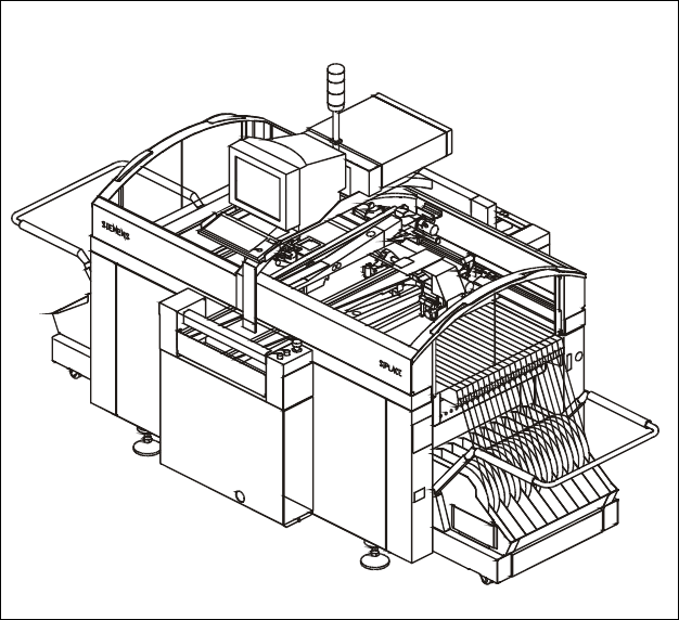
Description
The high-speed SMD placement
system SIPLACE S-25 HM com-
bines high placement speed with
flexibility and accuracy. In contrast
to classic chipshooters, a Collect
& Place procedure is applied here.
SIPLACE S-25 HM placement ma-
chines are equipped with two X-/Y-
main gantries. Each gantry featu-
res a star-shaped Collect & Place
placement head with either 12
or 6 nozzles.
The placement heads alternately
pick up components from the sta-
tionary component feeder and
place components on the PCB
which is also motionless. This has
distinct advantages:
§ Component tapes of all sizes
can be replenished by splicing a
new reel of components to the
end of a depleting reel. This eli-
minates machine stoppage due
to component replenishment.
§ Stationary, vibration-free feed-
ers ensure a reliable pick-up of
even the smallest components
(e.g., 0201 and 0402 chips).
§ Thanks to the flexible Collect
& Place Heads – whose ideal
nozzle set-up is automatically
specified – the travel can be
minimized and the sequence of
placement optimally adjusted.
§ Populating a stationary PCB
also prevents components from
shifting during placement.
Speed coupled with economic ef-
ficiency and set-up reliability is the
SIPLACE S-25 HM recipe for suc-
cess. The first components are al-
ready being picked up while the
PCB is being moved in. While one
Collect & Place Head is placing
components, the other one is
picking components up.
The product capability is enhanced
by optional add-on features such
as component bar code scanner,
automatic nozzle changer or
changeover tables which can be
set up outside the machine and
exchanged in a matter of minutes.
§ Additional changeover tables
enables the reduction of job set-
up time increasing machine
utilisation.
§ Dual Conveyor eliminates the
non-productive PCB loading
times thus increasing machines
operating efficiency.
§ Automatic nozzle changers for
both changeover and storage of
nozzles.
§ PCB Barcode Reader used for
product controlled production
changeover.
§ Component Bar Code Scanner
used for feeder set-up verifica-
tion.
§ To achive the best placement
quality we recommend to order
an 0201 enhance kit.
§ Ceramic Substrat Centering
§ Matrix Tray Changer (MTC) for
high speed IC-mounting
Machine Description
Technical Data
Type of placement head 12-Nozzle Collect & Place Head and/or
6-Nozzle Collect & Place Head
Number of gantries 2
Benchmark placement rate
a
12/12 25,000 cph
6/12 18,000 cph
6/6 17,000 cph
Component Range 0.6 x 0.3 mm
2
(0201) to 32 x 32 mm
2
Max. placement accuracy
(at 4 sigma)
a
90 µm (12-Nozzle C & P Head)
70/80 µm (6-Nozzle C & P Head)
PCB dimensions (L x W)
Single conveyor
Dual conveyor
50 x 50 mm
2
to 508 x 460 mm
2
/
2" x 2" to 20" x 18"
(optional up to 610 mm length)
50 x 50 mm
2
to 460 x 216 mm
2
/
2" x 2" to 18" x 8.5"
(optional up to 610 mm length)
Feeding capacity 118 tracks, 8 mm tape
Component table Quick changeover table with integrated wheels,
reel holder and scrap bin, SIPLACE MTC
Types of Feeder modules Tapes, Bulk Cases, Stick Magazines, Surftape
feeders, application-specific OEM feeders
Operating system Microsoft Windows / RMOS
Power 2 kW
Compr. air requirements 5.5 - 10 bar, 400 Nl/min, tube ½"
Vacuum pump (Option) 5.5 - 10 bar, 200 Nl/min, tube ½"
a) As defined in “Scope of Service and Delivery SIPLACE”.