Specification-SIPLACE-S25HM-eng - 第7页
5 Description Head Modul arity al lows the cus- tomer to specify the machi ne head configuration according to the component range output require- ments. The 6-Nozzle and the 12- Nozzle Collect & P lace Head c an be i…
4
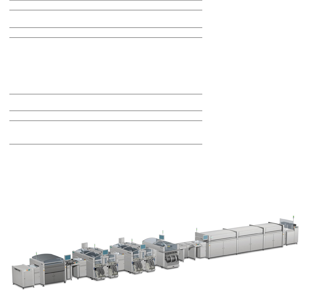
Bare
Board
Loader
Screen Printer
Reflow Oven
SIPLACE HS-60
SIPLACE S-25 HM
Magazine
Loader
Example of a SIPLACE Placement Line
SIPLACE HS-60
Description
Flexibility and adaptability charac-
terize the modular SIPLACE de-
sign. Each production line can be
individually composed of similar
and different modules.
Because of the small size and ro-
bust construction of the SIPLACE
modules, they can be recombined
quickly and easily to accommodate
changes in production require-
ments.
The SIPLACE family of placement
machines offers the right product
for each purpose – from the very
high-speed placement system
SIPLACE HS-60 to the high-speed
SMD placement system SIPLACE
S-25 HM and the flexible place-
ment system SIPLACE F
5
HM.
SIPLACE line-level optimization
tools generate single set-ups for
single products, single set-ups for
several products as well as several
set-ups for several products. Also,
product programs can be trans-
ferred from line to line even when
the machine configurations are dif-
ferent.
Line Design
Technical Data
System SIPLACE SMD placement lines
Modules SIPLACE HS-60 / SIPLACE S-25 HM /
SIPLACE F
5
HM / SIPLACE HF
PCB conveyor Automatic width adjustment
PCB dimensions (L x W)
Single conveyor
Dual conveyor
50 x 50 mm
2
to 508 x 460 mm
2
/
2" x 2" to 20" x 18"
(optional up to 610 mm length)
50 x 50 mm
2
to 460 x 216 mm
2
/
2" x 2" to 18" x 8.5"
(optional up to 610 mm length)
Ceramic substrate dimensions
(L x W)
50 x 50 mm
2
to 101.6 x 177.8 mm
2
2" x 2" to 4" x 7"
Placement speed Depends on layout of modules
Space required 4 m² / SIPLACE S & F modules
6.8 m² / SIPLACE HS module
6.0 m
2
SIPLACE HF module
5
Description
Head Modularity allows the cus-
tomer to specify the machine head
configuration according to the
component range output require-
ments. The 6-Nozzle and the 12-
Nozzle Collect & Place Head can
be interchanged to accommodate
changing manufacturing require-
ments.
The X/Y-gantry features two
placement heads: the 6-Nozzle or
the 12-Nozzle high-speed Collect &
Place Head.
The possible configuration choices
are:
§ Two 12-Nozzle Collect & Place
Heads.
§ Two 6-Nozzle Collect & Place
Heads.
§ One 6-Nozzle Collect & Place
Head and one 12-Nozzle
Collect & Place Head.
Placement head configuration can
also be changed in the field by or-
dering the respective head recon-
figuration kit (head included) and
nozzle changer.
Exchanging the Collect & Place
Heads requires reconfiguration of
the station software and recalibra-
tion of the machine by trained per-
sonnel. Also – if used – the auto-
matic nozzle changer has to be
replaced to match the head used.
The reconfiguration will take about
8 hours with a trained service
technician.
Changing a placement head and
reconfiguring a SIPLACE machine
when and where required allows
the customer to benefit from the
flexibility of different placement
heads without having to invest in
several SIPLACE machines.
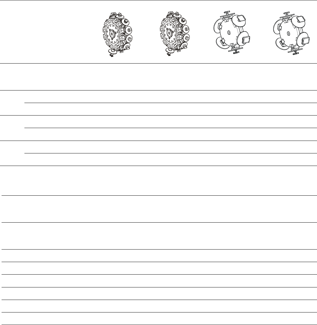
Placement Heads:
Head Modularity
Placement Heads for SIPLACE S-25 HM
6-Nozzle
Collect & Place
Head
12-Nozzle
Collect & Place
Head
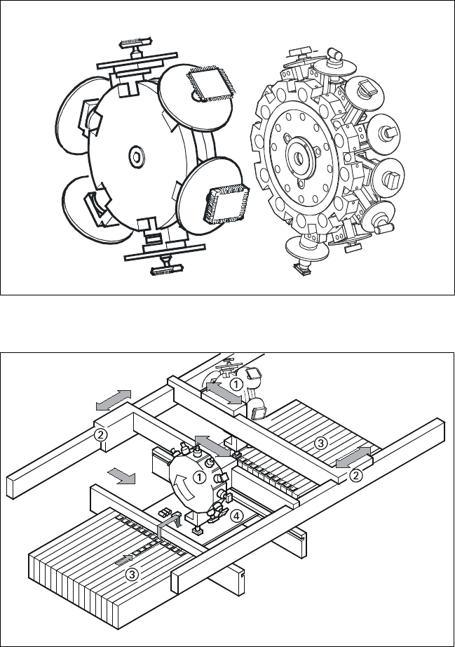
Placement Principle of SIPLACE S-25
HM
➀ 6-Nozzle or 12-Nozzle
Collect & Place Head
➁ X-/Y-Gantry System
➂ Fixed Component Supply
➃ Fixed PCB
6
Placement Heads: S-25 HM
Placement Accuracy
Component Range
Placement Accuracy
a
Placement Head
Placement Accuracy
12-Nozzle
Collect & Place Head
12-Nozzle
Collect & Place Head
with DCA (Option)
6-Nozzle
Collect & Place Head
6-Nozzle
Collect & Place Head
with DCA (Option)
X/Y Accuracy ± 67.5 µm ± 67.5 µm ± 60 µm ± 52.5 µm
3
Sigma
Rot.-Accuracy ± 0.525° ± 0.525° ± 0.225° ± 0.225°
X/Y Accuracy ± 90.0 µm ± 90.0 µm ± 80.0 µm ± 80.0 / 70.0 µm
a
4
Sigma
Rot.-Accuracy ± 0.700° ± 0.700° ± 0.400° ± 0.400°
X/Y Accuracy ± 135.0 µm ± 135.0 µm ± 120.0 µm ± 105.0 µm
6
Sigma
Rot.-Accuracy ± 1.050° ± 1.050° ± 0.450° ± 0.450°
a) As defined in “Scope of Service and Delivery SIPLACE”.
Component Range
12-Nozzle
Collect & Place Head
12-Nozzle
Collect & Place Head
with DCA (Option)
6-Nozzle
Collect & Place Head
at gantry 2
6-Nozzle
Collect & Place Head
with DCA (Option)
Component size
0.6 x 0.3 mm
2
b
to
18.7 x 18.7 mm
2
0.6 x 0.3 mm
2
b
to
13 x 13 mm
2
1.6 x 0.8 mm
2
to
32 x 32 mm
2
1.6 x 0.8 mm
2
to
13 x 13 mm
2
Max. component height 6 mm 6 mm 8.5 mm 8.5 mm
Max. component weight 2 gr 2 gr 5 gr 5 gr
Placement force 2.4 - 5.0 N 2.4 - 5.0 N 2.4 - 5.0 N 2.4 - 5.0 N
Performance See table on page 3 See table on page 3 See table on page 3 See table on page 3
Min. pitch lead / bump
c
500 / 350 µm 400 / 200 µm 500 / 560 µm 400 / 200 µm
Min. ball / bump diam.
c
200 µm 110 µm 320 µm 110 µm
b) 0201 (recommended to order the special 0201-kit).
c) Depends also on specification of components (quality, vision...)