00196351-06_UM_ACT_DE_EN.pdf - 第137页
ACT - Accurac y Check Tool / User Manual 09/2015 Edition 47 NOTICE ► Check the orientat ion of the inserted pla te if you see the f ollowing error me ssage (ACT cross cannot be measured). Figure 4-22: Error message c aus…
ACT - Accuracy Check Tool / User Manual 09/2015 Edition
46
4.2.3 Inserting the Plate
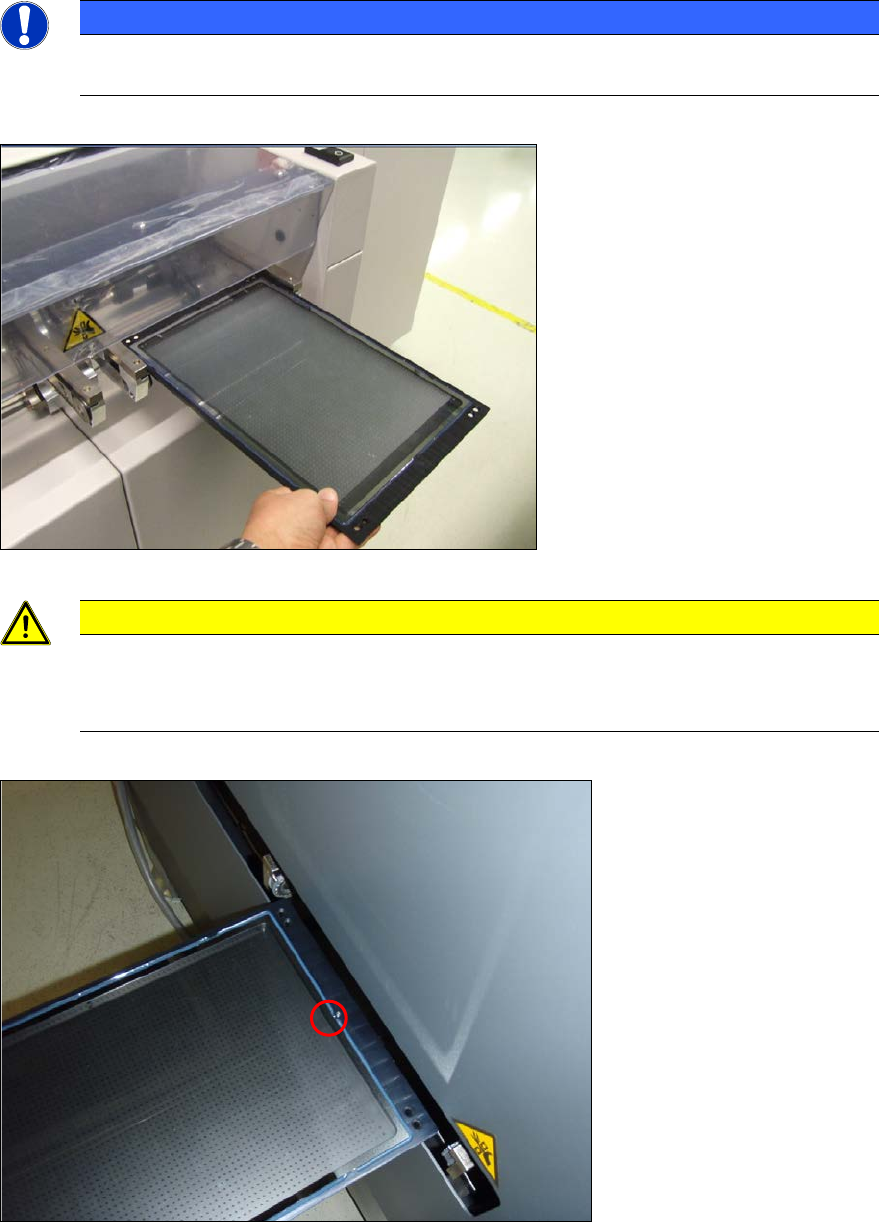
► Insert the glass plate with the incident light plate (black metal plate) underneath it in the input
section.
NOTICE
The measuring plate needs to be inserted so that the arrows marked on the plate show
in the transport direction.
Figure 4-20: Placing the measuring plate in the conveyor (example SIPLACE X4)
CAUTION
Caution for SX4 and DX4 machines:
The measuring plate needs to be inserted so that the arrows marked on the plate show
against the transport direction on the SX4 and DX4 machines.
Figure 4-21: Placing the measuring plate in the SX4 / DX4 conveyor with the calibration structure (ink spot forward)
ACT - Accuracy Check Tool / User Manual 09/2015 Edition
47
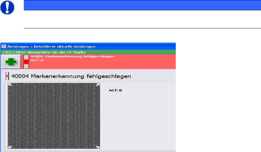
NOTICE
► Check the orientation of the inserted plate if you see the following error message
(ACT cross cannot be measured).
Figure 4-22: Error message caused by faultily inserted plate; example SW 705
ACT - Accuracy Check Tool / User Manual 09/2015 Edition
48
4.2.4 Loading the Plate into the Measuring Machine
4.2.4.1 D- and X-Series
On the SIPLACE D- and X-series machines the glass plate can be inserted into the conveyor by
opening the covers of the input section (extension kit) or the machine cover.
► Insert the plate directly into the input section of the measuring machine so that the sensor is
activated.
► Press Start.
The board is automatically moved into the placement area and gets placed.
Thereafter, the measurement is automatically started, see section 4.2.5.
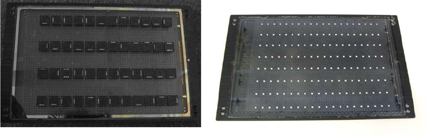
Figure 4-23 and Figure 4-24 show an assembled ACT plate, in one example with glass
components and in the other with ceramic components.
Figure 4-23: Measuring plate with placed glass comp. Figure 4-24: Measuring plate with placed ceramic comp.