00900045-01_ID_OIS_SIS_14.0_R16-2_DE_EN - 第51页
ASM OIS/SIS Databases 14.0 ( R16 - 2) / Interface De scription 12/2016 Edition 51 7 OIS State Ma chines 7.1 Machines wi th One Process ing Area ASM OIS displays to th e operator in w hich state the placem ent machine has…
ASM OIS/SIS Databases 14.0 (R16-2) / Interface Description 12/2016 Edition
50
6.8 Views of Version 1
6.8.1 V_RECIPE View
Supplies all columns of the RECIPE table in the following sequence:
strRecipe, strLine, strStation, ucConveyor, strBoard, strSetup, dtStart, dtEnd, lIdTrack
6.8.2 V_TRACK View
Supplies all columns of the TRACK table in the following sequence:
lIdTrack, sFeederType, ucTable, sTrack, ucTower, sLevel, sReceptacle, strPartNumber,
strComponentShape
6.8.3 V_DATAMODEL View
Supplies all columns of the DATAMODEL table in the following sequence:
strName, lLong, strString, dtTime, dDouble
ASM OIS/SIS Databases 14.0 (R16-2) / Interface Description 12/2016 Edition
51
7 OIS State Machines
7.1 Machines with One Processing Area
ASM OIS displays to the operator in which state the placement machine has been and for how
long. ASM OIS actually collects and records the events of the placement machine. The manner in
which the states are calculated from these events is shown at the end of this section. Each event is
assigned a timestamp from the station.
Explanation of terms
An action can set and/or clear one or more storage variables. An event has a unique name by
which it is identified. An event can be assigned an action which is always executed when this event
occurs. A state has a unique name. An action can be assigned to a state. This action is then
always executed when this state is entered. A storage variable exists for each state. Each storage
variable can be set or cleared. A state transition describes how the machine behaves when it
receives an event. A state transition can contain two different entries:
● The new state is specified directly.
● The new state is determined by reading the storage variable. If several storage variables are
set, the state with the highest priority is determined.
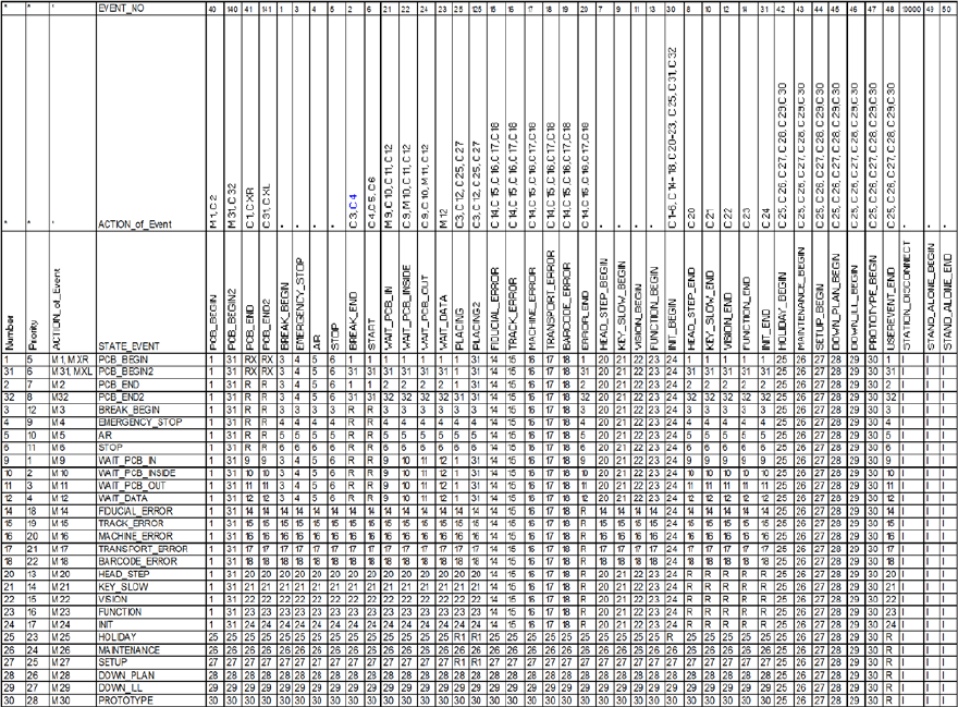
The following table describes a state machine with storage variables. The time a machine spends
in a particular state is assigned to that state.
Example
The machine is in state 10 OIS_WAIT_PCB_INSIDE (waiting for a PCB in the center conveyor).
Event 15 FIDUCIAL_ERROR now occurs. First, the action for the FIDUCIAL_ERROR event is
executed, "c14, c16, c17, c18". Secondly, the state transition is performed, i.e. the machine
switches to state 14 OIS_FIDUCIAL_ERROR. Thirdly, the action for the OIS_FIDUCIAL_ERROR
state is executed, "m 14".
NOTICE
Events 125, 140 and 141 in the downstream state automaton are artificially generated
events for conveyor track 2. This means, for example, that if the machine s
ends event 25
from conveyor track 2, it must be input to the state automaton as event 125. There is no
change for events on conveyor track 1.
ASM OIS/SIS Databases 14.0 (R16-2) / Interface Description 12/2016 Edition
52
Table 7-1: State machine with storage variables
M: Save state
C: Clear state
R: Read the state with the highest priority number
I: Ignore
R1: For machines with one placement area: read the state like R.
For machines with 2 placement areas: the state transition is executed for both placement areas.
RX: For machines with 2 placement areas: the state transition is executed for both placement areas R.
Placement process on 2 transport conveyors: The state changes to PCB_BEGIN or PCB_BEGIN2.
XR/XL: Status that indicates whether the placement process is on the right (XR) or left (XL) transport
conveyor.