00900045-01_ID_OIS_SIS_14.0_R16-2_DE_EN - 第56页
ASM OIS/SIS Databases 14.0 ( R16 - 2) / Interface De scription 12/2016 Edition 56 7.5 MTC / WPC Track In previous station software versions, the MTC / WP C was located on t rack 0 ( sTrack ) in the OIS database. In the S…
ASM OIS/SIS Databases 14.0 (R16-2) / Interface Description 12/2016 Edition
55
7.4.2 Station Software 7xx
The 7xx station software handles synchronous dual conveyor differently than the 605.xx software
does. This station software handles each board individually. This means that each board gets its
own board ID (IBoardNumber) and the events PCB-BEGIN and PCB_END are sent for each board.
OIS generates a database entry for each board in the BOARD table and an event entry for each
event in the EVENT table in the OIS database.
ASM OIS/SIS Databases 14.0 (R16-2) / Interface Description 12/2016 Edition
56
7.5 MTC / WPC Track
In previous station software versions, the MTC / WPC was located on track 0 (sTrack) in the OIS
database. In the SIS database these components were located on track 1 (sTrack). This caused a
difference between the OIS station view and the SIS line view.
As of the station software versions 605 and 701 the MTC / WPC is located on track 1 in both
databases.
NOTICE
The V_USEDCOMPONENTS6 view (see section 5.7.1) shows track 0 (sTrack) as
track 1.
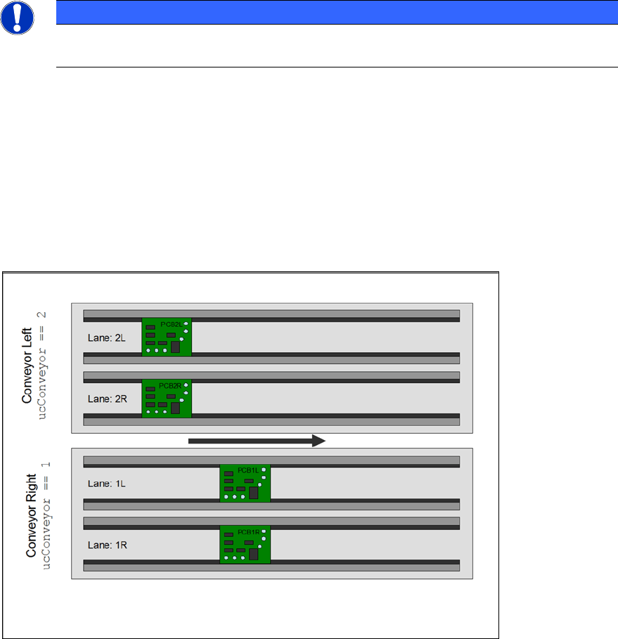
7.6 Quad Lane Support
The station software as of 702 supports the "Quad Lane" conveyor mode. This mode means that a
placement machine is equipped with two lanes per conveyor, i.e. each conveyor has two sub-
lanes. Each sub-lane can handle a PCB autonomously but not independently. The meaning of “not
independently” is, that the two lanes of a conveyor always run in synchronous mode, i.e. PCBs on
both lanes enter and leave a certain processing area at the same time.
Figure 7-2: Quad Lane
The sub-lane information can be found in the lSubConveyor column in the BOARD table of the OIS
database.
If the station does not run in "Quad Lane" conveyor mode, this entry contains the value "0". In case
of "Quad Lane" conveyor mode, this entry is either "1" for the right lane or "2" for the left lane.
ASM OIS/SIS Databases 14.0 (R16-2) / Interface Description 12/2016 Edition
57
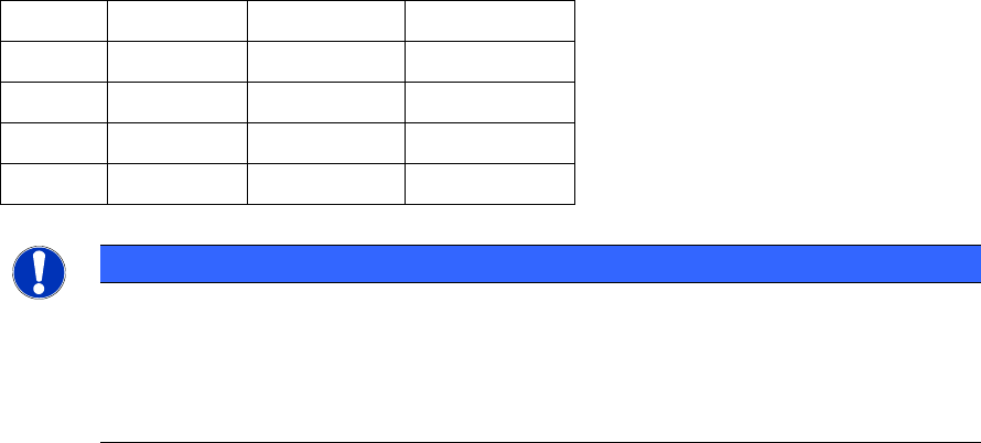
Applied to the example shown in the figure above, this would result in the following table entries.
strBoard ucConveyor lSubConveyor lBoardNumber
PCB2L 2 2 20
PCB2R 2 1 21
PCB1L 1 2 22
PCB1R 1 1 23
NOTICE
Please note that each PCB gets its own lBoardNumber. The values shown in the
lBoardNumber column are just examples and do not mean that the PCB on the left lane
on the left conveyor always gets the lowest number in "Quad Lane" conveyor mode. It
just means that each PCB gets a unique lBoardNumber.
This behavior is the same for synchronous and asynchronous mode.
The OIS server adds the following board specific database entries while a board gets produced.
EVENT table
● New Event: PCB_BEGIN when the production is started.
● New Event: PCB_END when the production is completed.
BOARD table
● A new row is added to the BOARD table describing the PCB.
USEDCOMPONENTS table
● A new row is added to the USEDCOMPONENT table for each component that has been
placed.
In "Quad Lane" conveyor mode these entries are written for each of the quad boards which can be
produced at a specific time.