252301 Issue 2.0.pdf - 第18页
GEM Manual for DEK Printers Capabilities I ssue 2.0 June 9th, 2011 page 18 of 156 5 Cap abiliti es Establis hing Co mm unic ations 5.1 Data Collecti on 5.2 Alarm Management 5.3 Control 5.4 Equipment Constan ts 5.5 Proces…

GEM Manual for DEK Printers Machine GEM Compliance
Issue 2.0 June 9th, 2011 page 17 of 156
GEM Requirement
I G
Print pressure error - front (ALID 81)
Print pressure error - rear (ALID 82)
Board fiducial 1 not found (ALID 83)
Board fiducial 2 not found (ALID 84)
Board fiducial 3 not found (ALID 85)
Screen fiducial 1 not found (ALID 86)
Screen fiducial 2 not found (ALID 87)
Screen fiducial 3 not found (ALID 88)
Select mark not found (ALID 89)
Bad vacuum tooling (ALID 90)
Start Modification >>>
Material RFID Tag Read Failed (ALID 91)
<<< End Modification
Verification item failed (ALID 92)
Product ID verification failed (ALID 93)
No cleaner paper (ALID 101)
No cleaner solvent (ALID 102)
Vortex cassette expired (ALID 103)
Paste cartridge empty (ALID 104)
Remote Commands
START
STOP
ERASE_LOG
ERASE_BATCH
ERASE_SESSION
RENAME_PRODUCT
ADJUST_PARAMETER
CLEAN
CLEAN_2
PASTE
PP-SELECT
CHANGE_SCREEN
KNEAD_PASTE
PAUSE

GEM Manual for DEK Printers Capabilities
Issue 2.0 June 9th, 2011 page 18 of 156
5 Capabilities
Establishing Communications 5.1
Data Collection 5.2
Alarm Management 5.3
Control 5.4
Equipment Constants 5.5
Process Program Management 5.6
Material Movement 5.7
Equipment Terminal Services 5.8
Error Messages 5.9
Clock 5.10
Limits Monitoring 5.11
Spooling 5.12
Verification and Traceability 5.13
GEM Manual for DEK Printers Capabilities
Issue 2.0 June 9th, 2011 page 19 of 156
5.1 Establish Communications
This capability enables control of transitions between the normal communications and
inoperative communication conditions. The current state of the communication link is
continuously displayed at the equipment operator console as shown in appendix B. Appendix B
also shows the operator controls provided for switching between communications enabled and
disabled.
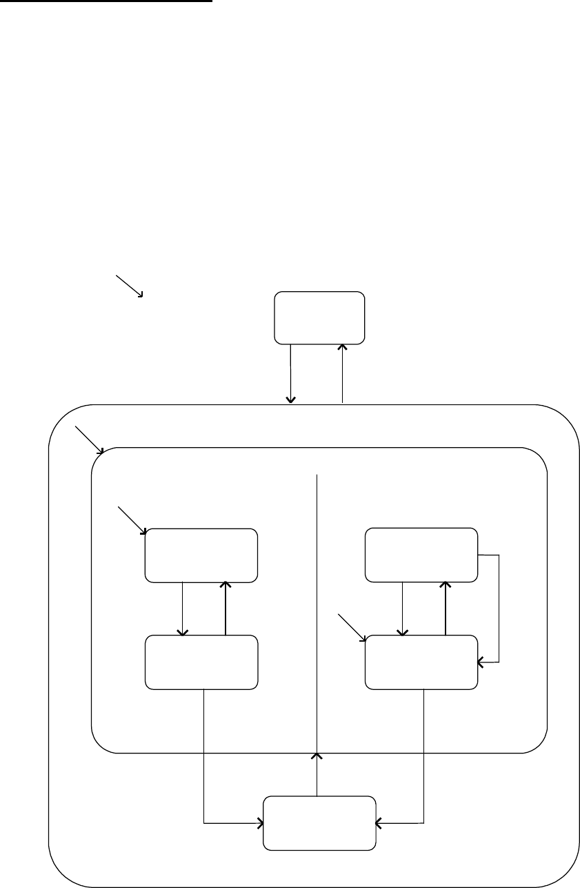
5.1.1 Communications State Model
The following diagram illustrates the level of communication with the equipment with regard
to the host system.
State Diagram:
C
DISABLED
System
Initialisation
.
COMMUNICATING
ENABLED
1
WAIT CRA
WAIT DELAY
WAIT TX.
COMPLETE
3
4
5
78
2
9
11
13
10
6
14
12
WAIT CR
FROM HOST
EQUIPMENT INITIATED CONNECTHOST INITIATED CONNECT
NOT COMMUNICATING