SIPLACE DX1DX2-Spec-设备性能参数-EN-DMS - 第32页
32 Digital SIPLACE Vision System The digital Vision system ensures fast and reliable component recognitio n, cou- pled with user-friendly ha n- dling. The s ystem identif ies each individu al compone nt by its geometry a…

31
Component Feeding
Waffle Pack Changer (WPC5/WPC6)
Technical Data
Electrical ratings
WPC5/WPC6 dimensions
Length x width
Height
For 900 mm PCB conveyor height
For 930 mm PCB conveyor height
For 950 mm PCB conveyor height
1520 mm x 360 mm
1430 mm
1460 mm
1480 mm
WPC5 weight
Basic configuration (with cassettes and waffle pack tray
carriers)
Fully configured (with WPTC and cassette with compo-
nents)
approx. 270 kg
approx. 320 kg
WPC6 weight
Basic configuration (with cassettes and waffle pack tray
carriers)
Fully configured (with WPTC and cassette with compo-
nents)
approx. 280 kg
approx. 330 kg
WPC5/WPC6 surface load 25 N/cm²
Weight of the waffle pack tray carrier 0.8 kg
Dimensions of the waffle pack tray carrier
(length x width x height) 360 mm x 260 mm x 6 mm
Dimensions of the waffle pack tray
length x width x height 347 mm x 235 mm x 15 mm
Height of waffle-pack tray, including component
WPC5
a
/WPC6
Mode - standard:
Mode - high components:
a) In WPC5 from serial number 1484, component height of up to 35 mm (maximum) possible.
to max. 29 mm
to max. 32 mm
Distance from level to level 17 mm (± 2 mm)
Storage capacity 28 Waffle pack tray carrier
Changeover time for waffle pack tray carrier
over 1 level
over 10 levels
over 27 levels
1.9 s
2.3 s
2.8 s
Supply voltage 3 x 200 V~ ± 10 %; 50/60 Hz (Japan)
3 x 208 V~ ± 10 %; 50/60 Hz (U.S.A)
3 x 230 V~ ± 10 %; 50/60 Hz
3 x 380 V~ ± 10 %; 50/60 Hz
3 x 400 V~ ± 10 %; 50/60 Hz (Europe)
3 x 415 V~ ± 10 %; 50/60 Hz
Nominal apparent power 1.5 kVA
Nominal active power 1.0 kW
Fuses 3 x 10 or 3 x 16 A

32
Digital SIPLACE Vision System
The digital Vision system
ensures fast and reliable
component recognition, cou-
pled with user-friendly han-
dling. The system identifies
each individual component
by its geometry and color.
Even complex component
shapes, such as flip chip or
CCGA are detected with high
reliability.
This component recognition
check is performed in a sin-
gle step, with no extra time
involved but with optimum
scanning of each individual
component.
This digital Vision system is
not only used in the compo-
nent cameras but also in the
PCB camera. In addition to
the precise recognition of
components, this also guar-
antees reliable detection of
inkspots and PCB fiducials.
The benefits at a glance:
• Extremely fast and reliable
component recognition
• Shortest cycle times
• Robust measurement
based on the geometry
and color
• Straightforward program-
ming
• Offline programming of
component shapes
• Rapid introduction of new
products (NPI)
• Open architecture allows
you to quickly adapt to
new requirements
• Optimum placement
results based on individ-
ual measurement of each
component
The SIPLACE Vision sys-
tem offers inspection rou-
tines and functions to
enhance the quality of com-
ponent recognition.
The benefits at a glance:
• Maximum placement
quality
• High first pass yield
• Reduction of operating
costs
Digital vision cameras
SIPLACE SpeedStar camera, type 23
SIPLACE 12 segment C&P camera, type 28
SIPLACE 12 segment C&P camera, type 30
SIPLACE TwinStar standard camera, type 36
SIPLACE TwinStar, type 33
SIPLACE TwinStar high resolution camera, type 25
SIPLACE PCB camera, type 34
Examples of digital vision system analysis times
Evaluation times only play a role in the P&P process.
01005 9 ms
PLC44 17 ms
BGA 225 balls 18 ms
33
Digital SIPLACE Vision System
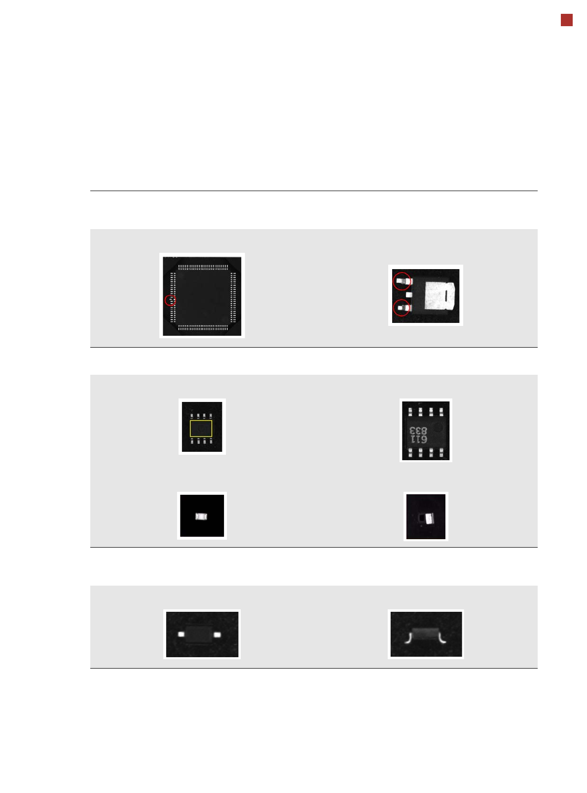
Checking the Component Quality
Overview of Key Functions
Recognizing the collinearity of components
Damaged or bent leads are recognized. This helps avoid solder-free connections during the subsequent solder-
ing process.
Damaged leads Damaged leads
Recognizing flipped (face down) or upright components
Both chip and IC component shapes (e.g. SOT) recognized in flipped (turned face down) or upright state.
SOT OK SOT “face down”
Flipped chip Chip upright
Checking the lead width
The optical checking of the lead width recognizes tilted or damaged leads. This helps to recognize e.g. diodes
with tilted leads.
Lead width OK Tilted lead