Specification SIPLACE CA-Series2014版 - 第14页
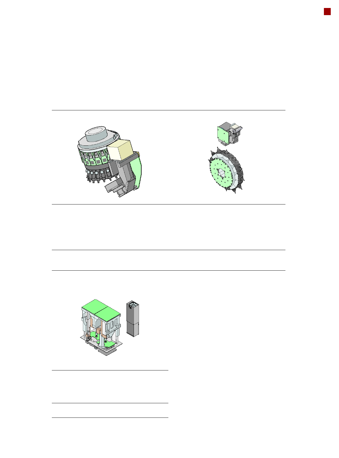
14 Placement Heads SIPLACE SpeedStar (C&P20 M) SIPLACE SpeedS tar (C&P20 M) With component camera type 41 Component range a a) Please note that the placeable component range is also affected by the pad geometry, …
13
Placement Heads
Standard Functions / Options
SIPLACE SpeedStar (C&P20 M) SIPLACE MultiStar (CPP)
Standard-
functions
High-resolution camera, vacuum
sensor, force measurement,
component sensor, integrated
turning station per segment,
PCB warpage check, individual
image of each component
Standard-
functions
High-resolution camera, vac-
uum sensor, force measure-
ment, component sensor,
integrated turning station per
segment, PCB warpage check,
individual image of each com-
ponent
Options Nozzle changer, special nozzles Options Nozzle changer, special noz-
zles, stationary fine-pitch cam-
era
SIPLACE TwinStar (TH)
Standard-
functions
Stationary fine pitch camera,
vacuum sensor, force measure-
ment, nozzle changer, PCB
warpage check, individual image
of each component
Options Stationary flip chip camera, spe-
cial nozzles, grippers
14
Placement Heads
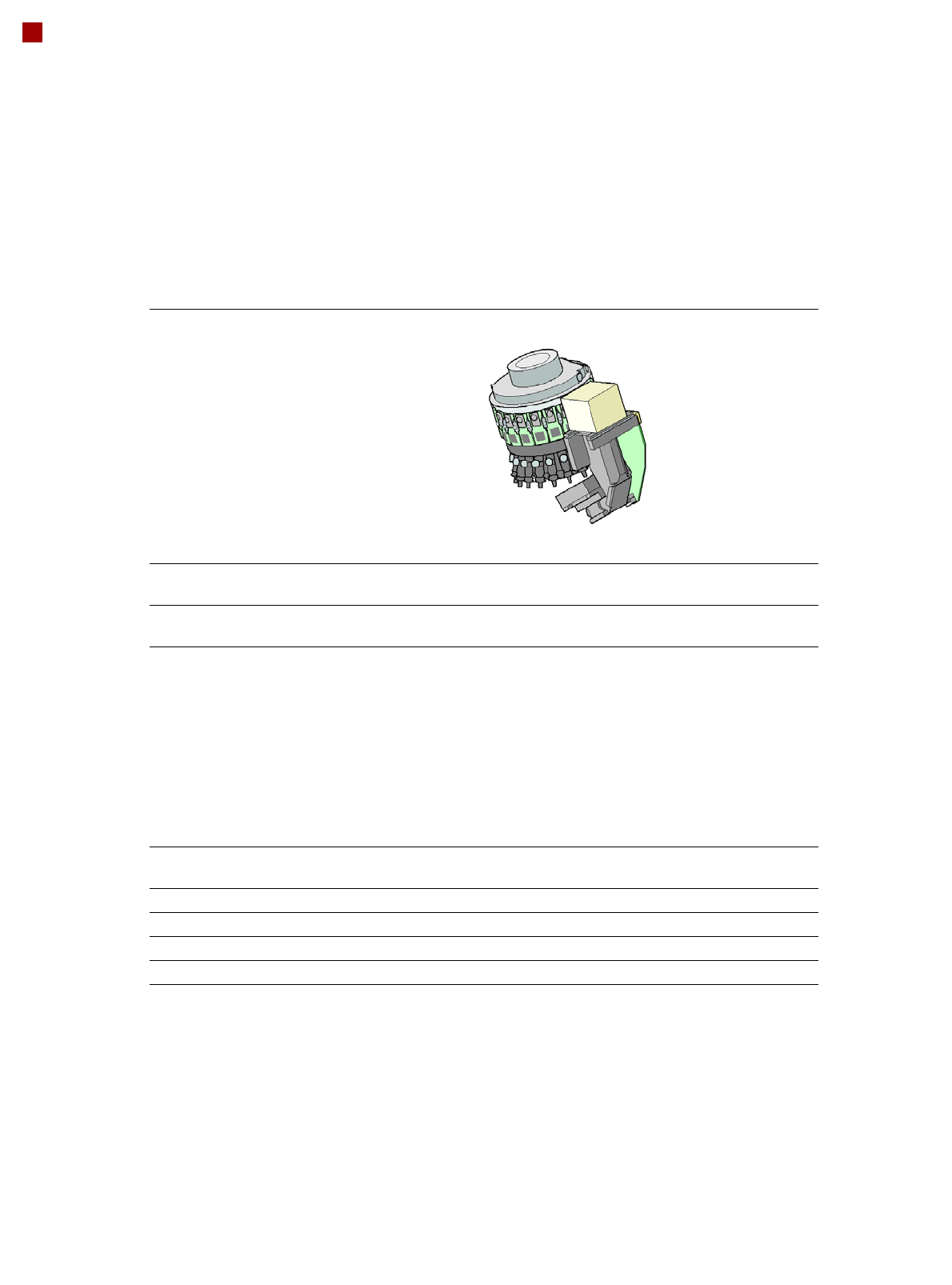
SIPLACE SpeedStar (C&P20 M)
SIPLACE SpeedStar (C&P20 M)
With component camera
type 41
Component range
a
a) Please note that the placeable component range is also affected by the pad geometry, the customer-spe-
cific standards, the component packaging tolerances and the component tolerances.
03015 to 2220, Melf, SOT,
SOD, Bare-Die, Flip-Chip
Component spec.
Max. height
Min. lead pitch
Min. lead width
Min. ball pitch
Min. ball diameter
Min. dimensions
Max. dimensions
Max. weight
4 mm
0.08 mm
0.03 mm
0.10 mm
0.05 mm
0.3 mm x 0.15 mm
6 mm x 6 mm
1 g
Programmable set-down
force
1.5 - 4.5 N
Nozzle types 10xx, 11xx, 12xx
X/Y accuracy
(SMT) ± 20µm / 3σ
X/Y accuracy
(CA)
b
b) 10μm at 3σ in the placement process; Option eWLB on request.
± 10µm / 3σ
Angular accuracy ± 0.2° / 3σ
15
Placement Heads
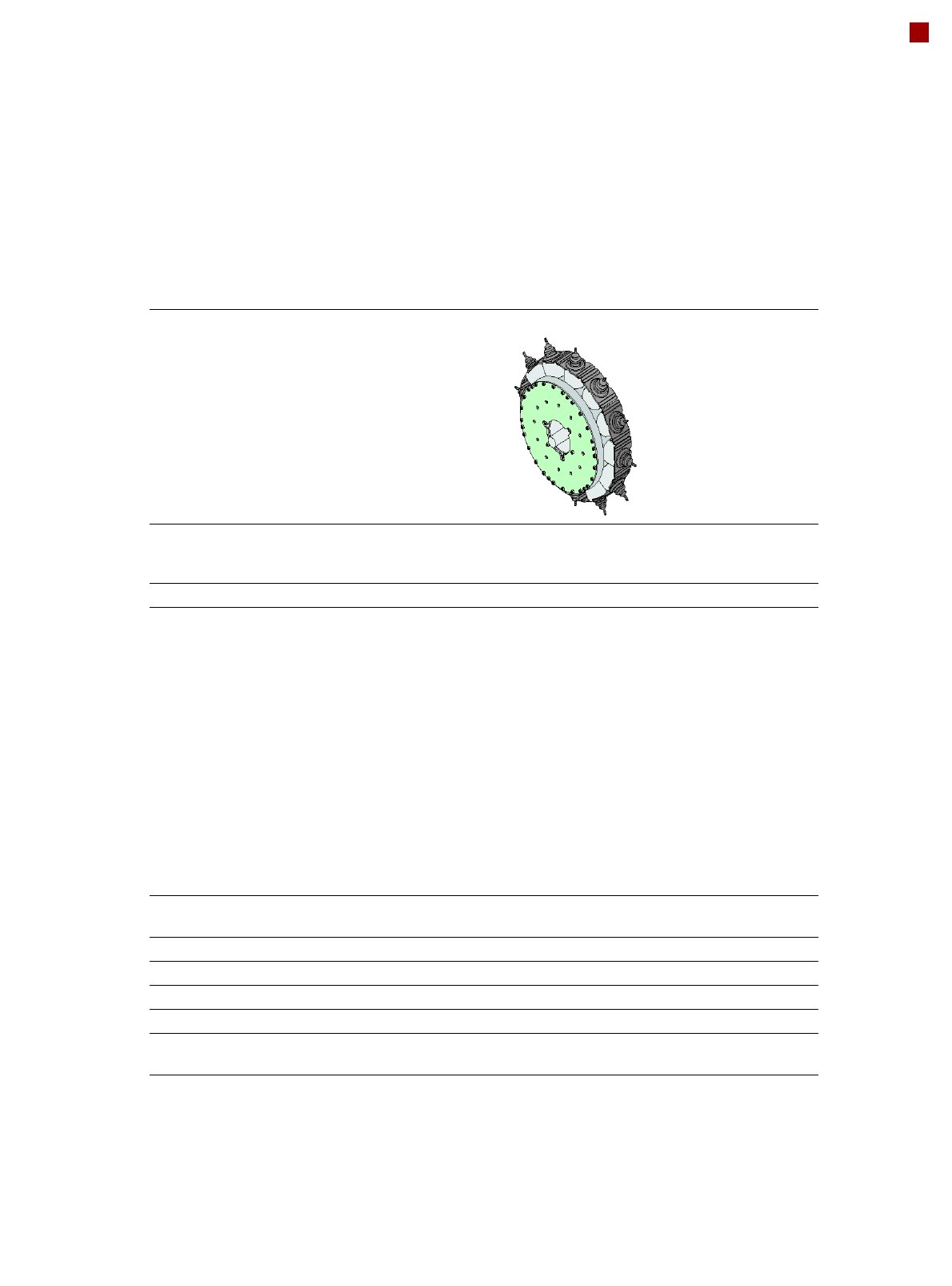
SIPLACE MultiStar (CPP)
SIPLACE MultiStar (CPP)
With component camera type 30 With component camera
type 33
(stationary camera)
a
a) Not in conjunction with SWS and not on location 2/4.
Component range
b
b) Please note that the placeable component range is also affected by the pad geometry, the customer-spe-
cific standards, the component packaging tolerances and the component tolerances.
03015 mm to 27 mm x 27 mm 0402 to 50 mm x 40 mm
Component spec.
Max height
c
Max. height
d
Min. lead pitch
Min. lead width
Min. ball pitch
Min. ball diameter
Min. dimensions
Max. dimensions
Max. weight
c) CPP head: in low installation position (stationary component camera not possible).
d) CPP head: in high installation position
6.0 mm
8.5 mm
0.3 mm
0.15 mm
0.25 mm
e
0.35 mm
f
0.14 mm
e
0.20 mm
f
0.3 mm x 0.15 mm
27 mm x 27 mm
4 g
e) For components < 18 mm x 18 mm
f) For components ≥ 18 mm x18 mm
11.5 mm
0.3 mm
0.15 mm
0.35 mm
0.2 mm
1.0 mm x 0.5 mm
50 mm x 40 mm
8 g
Programmable set-down
force
1.0 - 10 N 1.0 - 10 N
Nozzle types 20xx, 28xx 20xx, 28xx
X/Y accuracy
g
g) The SIPLACE benchmark value is measured during the machine acceptance tests. It corresponds to the
conditions set out in the SIPLACE scope of service and supply.
± 25 µm / 3σ ± 25 µm / 3σ
Angular accuracy ± 0.4° / 3σ
h
, ± 0.5° / 3σ
i
h) Component dimensions between 6 mm x 6 mm and 27 mm x 27 mm.
i) Component dimensions smaller than 6 mm x 6 mm.
± 0.2° / 3σ
Illumination levels 5 6
Possible illumination
level settings
256
5
256
6