Specification SIPLACE CA-Series2014版 - 第19页
19 Placement Heads Nozzle Changers Technical Data Nozzle change r for the SIPLACE SpeedSt ar Number of magazines a a) All magazines in the nozzl e changer must be configured. 6 Number of nozzle holders 72 S tandard confi…
18
Placement Heads
Nozzle Changers
Description
Nozzle changers increase
the flexibility of the placement
heads when it comes to pro-
cessing different compo-
nents. The
nozzle configuration can be
quickly modified for new
placement jobs. Precisely
defined positions and perfect
nozzle seat in the garage
ensure minimum radial
eccentricity on the placement
head.
The nozzle changer for the
MultiStar and the SpeedStar
is fitted with a monitoring cir-
cuit. which checks whether
the nozzle magazine is
seated correctly on the
mount. In addition, the nozzle
changers recognize whether
the magazines are for 1xx,
20xx or 28xx nozzles by the
code.
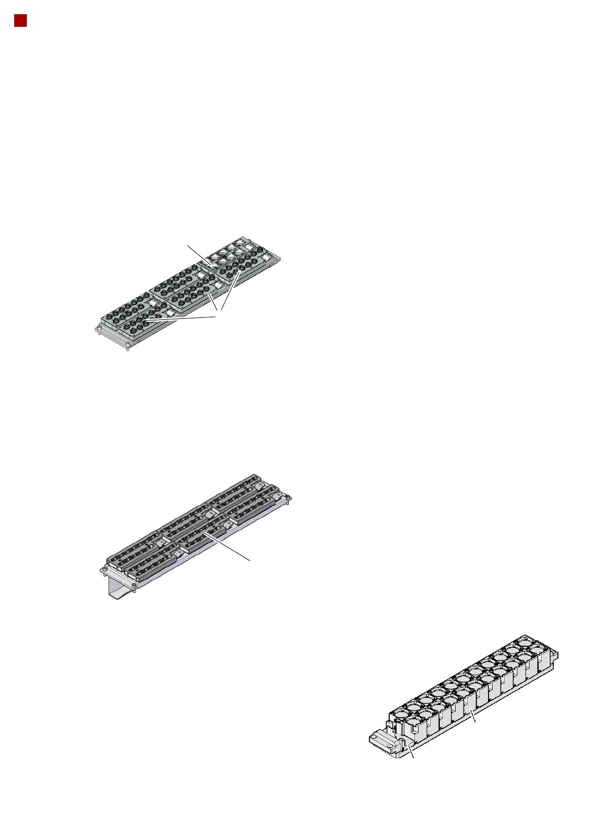
Nozzle changer for the SIPLACE MultiStar and
SIPLACE SpeedStar
Magazine for two
standard nozzles
Magazine for one special nozzle, gripper
Nozzle changer for the SIPLACE TwinStar
1 magazine for 9 nozzles
of type 28xx
5 magazines for 12 nozzles
of type 20xx
6 magazines for 12 nozzles of
type 10xx, 11xx or 12xx
Nozzle changer for the SIPLACE SpeedStar

19
Placement Heads
Nozzle Changers
Technical Data
Nozzle changer for the SIPLACE SpeedStar
Number of magazines
a
a) All magazines in the nozzle changer must be configured.
6
Number of nozzle holders 72
Standard configuration
Nozzle changer on X table
Nozzle changer on SWS
6 magazines with 72 nozzle garages in row 1 only
6 magazines with 72 nozzle garages in row 1
6 magazines with 72 nozzle garages in row 2
Nozzle types 10xx, 11xx, 12xx
Compressed air connection 0.45 MPa (4.5 bar)
Nozzle changer for the SIPLACE MultiStar
Number of magazines
a
6
Number of nozzle holders 60 (20xx nozzles)
9 (28xx nozzles)
SpeedStar: 72 (10xx, 11xx, 12xx nozzles)
Standard configuration
Nozzle changer on X table
Nozzle changer on SWS
6 magazines with 72 nozzle garages in row 1
6 magazines with 72 nozzle garages in row 2
6 magazines with 72 nozzle garages in row 1
6 magazines with 72 nozzle garages in row 2
Nozzle types 10xx, 11xx, 12xx
20xx, 28xx
Compressed air connection 0.45 MPa (4.5 bar)
Nozzle changer for the SIPLACE TwinStar
Number of magazines
max. 12 magazines for max. 24 nozzle garages
max. 10 magazines for max. 20 nozzle garages
Number of nozzle holders may be freely configured
Nozzle types 4xx with adapter
5xx (standard)
9xx with adapter
Special nozzle, gripper
Compressed air connection 0.45 MPa (4.5 bar)
20
PCB Conveyor
Single Conveyor
Description
For placement, the PCB is
clamped from below. The
distance between the top of
the PCB and the placement
head thus remains un-
changed for each PCB, and
is not dependent on the
thickness of the PCB. The
placement rate is thus inde-
pendent of the PCB thick-
ness.
Since the distance between
the PCB surface and the
PCB camera remains the
same, the PCB camera is al-
ways focused on the PCB
surface with the same clarity.
The PCB fiducial contours
are optimally mapped on the
CCD chip of the PCB cam-
era.
The inline PCB conveyor
system quickly adapts to a
wide range of PCB widths.
The setting is made using the
placement program or via
the station software menu.
The width of the PCB con-
veyor is monitored by an in-
tegral control circuit.
The machine height can be
selected to allow the ma-
chines to be integrated into
lines with a conveyor height
of 900, 930 or 950 mm.
The communication between
the PCB conveyors of the in-
dividual machines is via a
SMEMA interface (optional
Siemens interface).
The fixed transport side can
be located on the left or right
for both the dual conveyor
and the single conveyor.
With this conveyor, the fixed
side can be easily switched
from right to left or vice versa.
Movement and clamping of
the PCBs are monitored.
Once the board has reached
the placement area and has
passed the light barriers, it is
braked. A laser light barrier
records the position of the
board. As soon as the board
has reached its target posi-
tion, the conveyor belt is
stopped and the board is
clamped from below. The
placement process then
starts immediately.
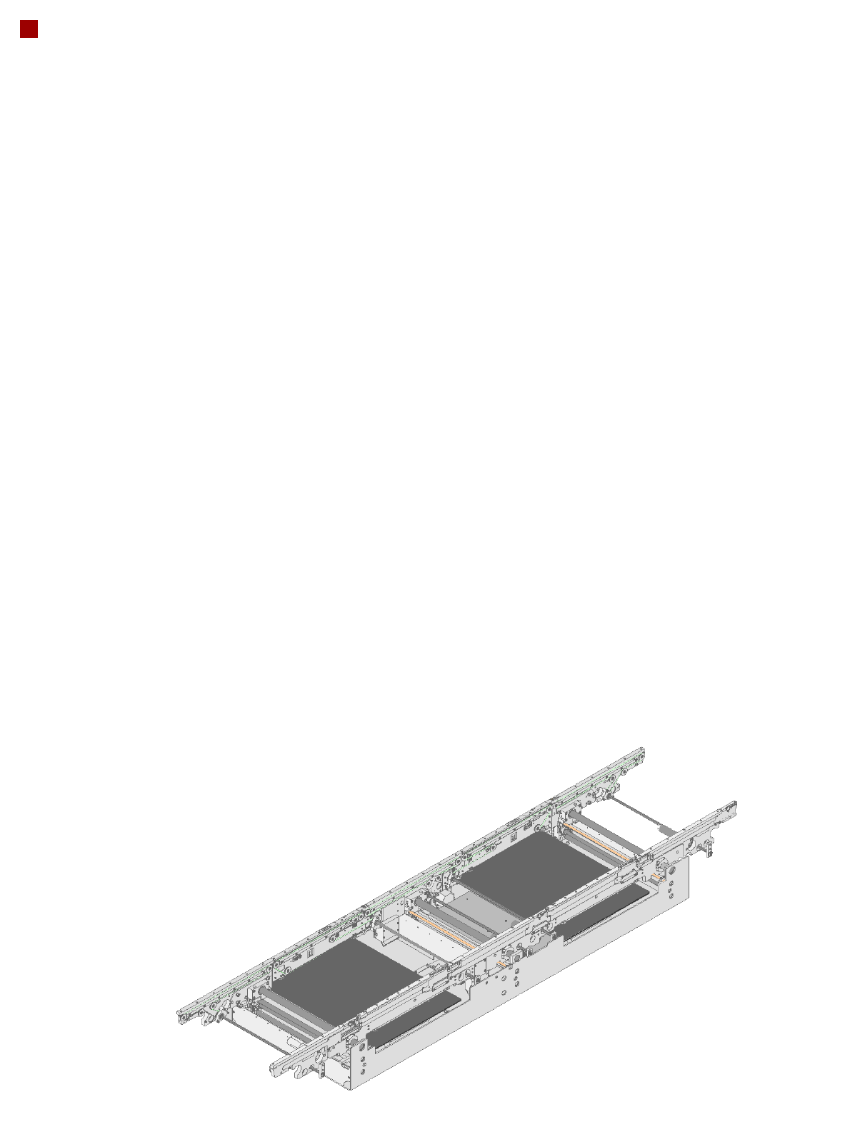
Placement area 1
Placement area 2
Output conveyor
Intermediate conveyor
Input conveyor