Specification SIPLACE CA-Series2014版 - 第28页
28 Component Feeding SIPLACE Wafer System The new SIPLACE W afer System (SWS) p rovides a fully automatic wafer an d chip handling system. The SWS is completely inte- grated into the locations of the SIPLACE CA placement…
27
Component Feeding
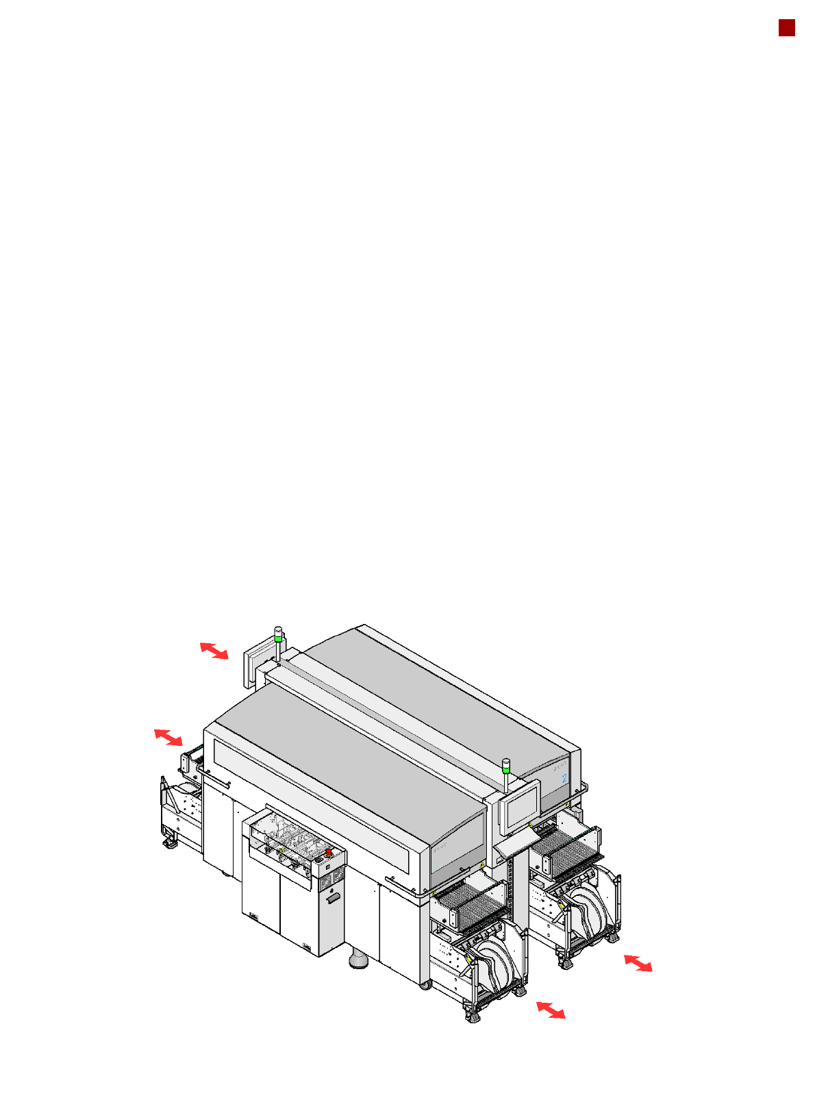
SIPLACE X-Series Component Trolley
Description
The component trolleys are
stand-alone modules that
can be set up with feeder
modules at an external setup
area. Up to four component
trolleys can be docked onto
the machine. A component
changeover table can be re-
placed with just a short inter-
ruption of the production
process. The chassis runs
smoothly and is easy to
maneuver.
The changeover table has a
capacity of up to 40 locations
for 8 mm X tape feeder mod-
ules. The total capacity with
four component trolleys is
thus 160 tracks x 8 mm.
Dummy feeder modules are
used at unassigned locations
to protect the operators.
The component feeders are
at rest during the placement
process - allowing tapes to
be spliced without stopping
the machine.
With the help of an optional
component barcode reader
and the Setup Center option,
the barcodes on the tape
reels can be read and
checked, thus guaranteeing
that the components are allo-
cated to the correct tracks.
Location 1
Location 3
Location 2
Location 4
28
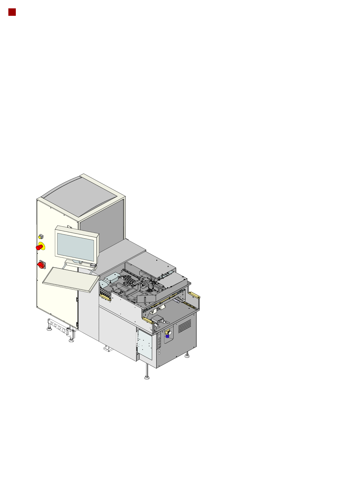
Component Feeding
SIPLACE Wafer System
The new SIPLACE Wafer
System (SWS) provides a
fully automatic wafer and
chip handling system.
The SWS is completely inte-
grated into the locations of
the SIPLACE CA placement
system. Each location can be
equipped with an SWS or an
X table.
The SWS functions like a
feeder for the SIPLACE sys-
tem and transports the dies
from the wafer to a single,
fixed pickup position for the
placement head.
The placement head picks
the die up from the SWS and
places this on the board as
done during SMD handling.
The SWS is shown as a spe-
cial feeder type in SIPRO.
The SIPLACE CA system is
programmed as usual for the
SIPLACE X series.
The die handling is pro-
grammed via the SWS GUI.
The main parameters to be
programmed are as follows:
– Wafer and die dimen-
sions
– Die recognition
– Die ejection parameters
– Wafer map system
– Link to the component
programmed in SI-
PLACE Pro
29
Component Feeding
SIPLACE Wafer System
Technical Data
Dimensions and weight
Length x width 1.580 mm x 720 mm
Weight 350 kg
Electrical ratings
Supply voltage 3 x 400 VAC, 50 Hz (Europe)
3 x 208 VAC, 60 Hz (USA)
Total output 1.5 kW
Rated current 2.7 A at 3 x 400 VAC
4.2 A at 3 x 208 VAC
Fuse 3 x 16 A
Nominal current consumption of largest consumer 2 A
Noise emissions
Max. noise emissions 74 dB (A)
Permissible environmental impact
Room temperature Between 15°C and 35°C
Atmospheric humidity 30 - 75 %
(No higher than 45% on average to
prevent any possibility of condensa-
tion on the machine)