Specification SIPLACE CA-Series2014版 - 第33页
33 Component Feeding Dummy Feeder Modules Dummy feeder module for one track Danger To ensure that your SIPLACE placement machine runs safely, a feeder must be assigned to every location on the componen t trolley. If you …
32
Component Feeding
Alternative SIPLACE Feeder Modules
Technical Data
Linear vibratory feeder
type 3
Packaging style
track number and width of
tracks
Stick magazines
X component trolley
a
3 x ≤ 9.5 mm
2 x ≤ 15 mm
1 x ≤ 30 mm
Occupies 3 locations of an
8 mm X feeder module
Linear Dipping Unit
(LDU X)
b
for X component trolley
Occupies 9 locations of an
8 mm X feeder module,
max. 1 per head
SIPLACE Glue Feeder Occupies 5 locations of an
8 mm X feeder module,
max. 1 per head
a) With X adapter
b) With restrictions
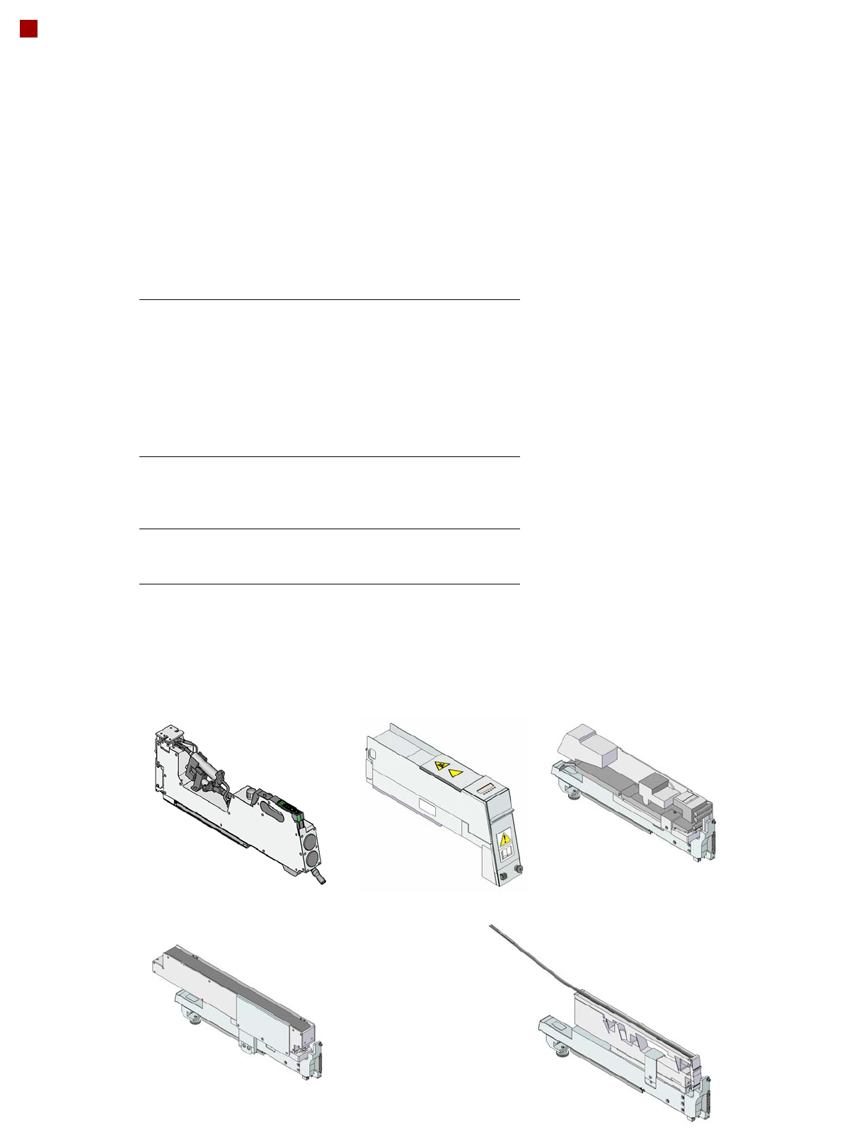
Description
Linear vibratory feeders pro-
cess components in stick
magazines. These can be
easily configured with the X
adapter for use with the X
component trolley. They can
be refilled without stopping
the machine. The X adapter
also allows you to set up the
label presenter and the
reject conveyor on the X
component trolley. The LDU
X is suitable for dip fluxing of
flip chips, CSP (Chip Scale/
Size Packages) and for coat-
ing flip chip bumps with iso-
tropic conductive adhesive.
The SIPLACE Glue Feeder
allows you to position dots of
adhesive on a component,
before it is placed.
Reject conveyor
with X adapter
Glue Feeder
Linear vibratory feeder, type 3
with X adapter
Linear Dipping Unit
(LDU X)
Label presenter
with X adapter
33
Component Feeding
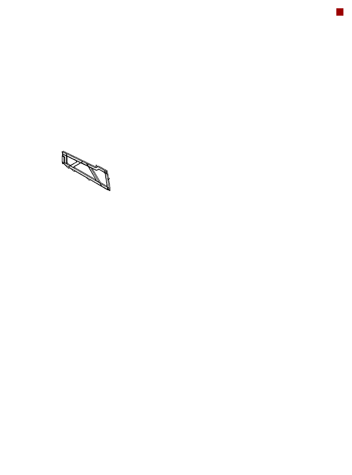
Dummy Feeder Modules
Dummy feeder module for one track
Danger
To ensure that your SIPLACE placement machine runs safely, a feeder must be assigned to
every location on the component trolley.
If you do not have enough feeder modules, then you should use dummy feeder modules as
space holders.
Dummy feeder module for the component trolley of the X series (CA series)
The dummy feeder module for the SIPLACE X series occupies one track on the component
trolley.

34
Vision Sensor Technology
PCB Position Recognition
Description
Different fiducial shapes
prove to be optimal depend-
ing on the condition of the
surface. When using bare
copper surfaces with low oxi-
dation, it is advisable to take
the single cross, as the high
amount of information pro-
vided helps achieve the
greatest accuracy. Rectan-
gle, square and circle are
less "informative" but save
space and can even be used
when oxidation is at an
advanced stage. Circle or
square are advisable for tin-
plated structures as the ratio
of the fiducial dimensions to
the presolder thickness is
particularly favorable.
Fiducial criteria
Locate 2 fiducials
Locate 3 fiducials
X/Y position, rotation angle, mean PCB distortion
Additional: shearing, distortion separately in X and Y direc-
tion
Locate 2 fiducials
X/Y position, rotation angle without stretch
a
.
a) Option: Wafer Level Fan Out (WLFO)
Fiducial shapes Synthetic fiducials: circle, cross, square, rectangle, dia-
mond, circular, square and rectangular contours, double
cross, pattern: any
Fiducial surface:
Copper
Tin
Without oxidation and solder resist
Warpage of fiducial ≤ 1/10 of structure width, both with good
contrast to environment
Dimensions of patterns
Min. size
Max. size
0.5 mm
3 mm
Fiducial environment Clearance around reference fiducial not necessary if there
is no similar fiducial structure in the search area
Dimensions of synthetic fiducials
Min. X/Y size for circle and rectangle: 0.25 mm
Min. X/Y size for annulus and rectangle: 0.3 mm
Min. X/Y size for cross: 0.3 mm
Min. X/Y size for double-cross: 0.5 mm
Min. X/Y size for rhombus: 0.35 mm
Min. frame width for annulus and rectangle: 0.1 mm
Min. bar width / bar distance for cross, double-cross: 0.1 mm
Max. X/Y size for all fiducial shapes: 3 mm
Max. bar width for cross, double-cross: 1.5 mm
Min. tolerances, general: 2% of nominal dimension
Max. tolerances, general: 20% of nominal dimension