Specification SIPLACE CA-Series2014版 - 第46页
46 Technical Data SMEMA Interface - Signal Sequence 1. After swit ching on t he statio n Transport direction Belt n Belt n+1 PCB sensor PCB sensor Station n transports PCB to the transfer position Belt n running Belt n+1…

45
Technical Data
SMEMA Interface - Connector Assignment
Signal interface (14-pole connecting socket, interface standard 1.2)
Upstream station X1 Downstream station X2
Pin 1 NOT READY + Pin 1 NOT READY +
Pin 2 NOT READY – Pin 2 NOT READY –
Pin 3 BOARD AVAILABLE + Pin 3 BOARD AVAILABLE +
Pin 4 BOARD AVAILABLE – Pin 4 BOARD AVAILABLE –
Pin 5 Not used Pin 5 Not used
Pin 6 Not used Pin 6 Not used
Pin 7 Not used Pin 7 Not used
Pin 8 Reserved Pin 8 Reserved
Pin 9 Reserved Pin 9 Reserved
Pin 10 Reserved Pin 10 Reserved
Pin 11 Reserved Pin 11 Reserved
Pin 12 Reserved Pin 12 Reserved
Pin 13 Reserved Pin 13 Reserved
Pin 14 Reserved Pin 14 Reserved
46
Technical Data
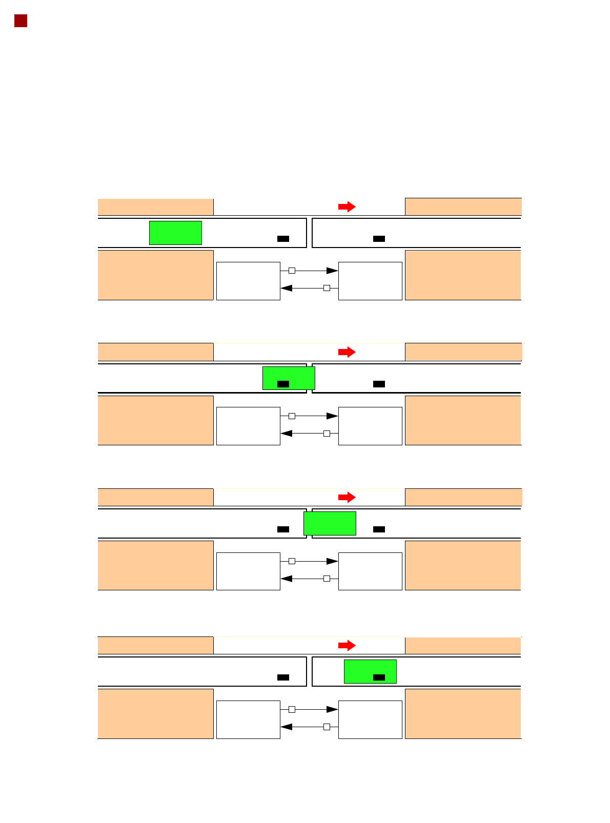
SMEMA Interface - Signal Sequence
1. After switching on the station
Transport direction
Belt n Belt n+1
PCB sensor PCB sensor
Station n transports PCB
to the transfer position
Belt n running Belt n+1 stopped
BOARD AVAIL-
ABLE
Permission
Station n+1
is not ready
1
0
2. The PCB transfer has started
Transport direction
Belt n Belt n+1
PCB sensor
Station n transfers
PCB to Station n+1
Belt n running Belt n+1 running
Station n+1 expects
PCB from station n
3. PCB is transferred
Transport direction
Belt n Belt n+1
PCB sensor PCB sensor
Station n has
just transferred the PCB
Belt n stopped Belt n+1 running
Station n+1 expects PCB
from station n, but PCB
has not yet arrived.
PCB sensor
4. PCB transfer is complete
Transport direction
Belt n Belt n+1
PCB sensor PCB sensor
Station n
Belt n stopped Belt n+1 running
Station n+1
PCB arrived
Request
NOT READY
BOARD AVAIL-
ABLE
Permission
1
1
Request
NOT READY
BOARD AVAIL-
ABLE
Permission
0
1
Request
NOT READY
BOARD AVAIL-
ABLE
Permission
0
0
Request
NOT READY
To start a new PCB transfer, both signals must be "0" for at least 50 ms.

47
Technical Data
Electrical Ratings and Compressed Air Supply
Electrical ratings
Supply voltage 3 x 200 V~ ± 5 %; 50/60 Hz (Japan)
3 x 208 V~ ± 5 %; 50/60 Hz (U.S.A.)
3 x 230 V~ ± 5 %; 50/60 Hz
3 x 380 V~ ± 5 %; 50/60 Hz
3 x 400 V~ ± 5 %; 50/60 Hz (Europe)
3 x 415 V~ ± 5 %; 50/60 Hz
Fuse protection (machine) 3 x 32 A (3 x 200 V~ / 3 x 208 V~ / 3 x 230 V~)
3 x 16 A (3 x 380 V~ / 3 x 400 V~ / 3 x 415 V~)
Mains connection
(machine)
Cable 5 x 6 mm² with CEKON connector 5 x 32 A (3 x 200 V~ / 208 V~ / 230 V~)
Cable 5 x 4 mm² with CEKON connector 5 x 16 A (3 x 380 V~ / 400 V~ / 415 V~)
Fuse protection (SWS)
3 x 16 A (3 x 208 V~ / 3 x 230 V ~ / 3 x 380 V~ / 3 x 400 V~ / 3 x 415 V~)
Mains connection (SWS)
a
a) 1 mains connection required per SWS.
Cable 4 x 2.5 mm² with CEE connector 5 x 16 A (400 V~)
Nominal apparent power
SIPLACE CA4: 5.0 kVA
SWS: 0.7 kVA
Rated current consump-
tion
SIPLACE CA4: 11.3 A / 3 x 400 V~
SWS: approx. 1.8 A / 3 x 400 V~
Compressed air supply
Compressed air pressure
values
p
min
p
max
0.5 MPa = 5.0 bar
1.0 MPa = 10 bar
Operating pressure 0.48 MPa ± 0.025 MPa (4.8 bar ± 0.25 bar)
Compressed air connec-
tion
R 3/4" inner thread (pipe thread) with 1/2" hose connection
Compressed air consumption
a
Placement head configuration Compressed air
consumption
b
with vacuum pump
Compressed air
consumption
without vacuum
pump
c
SIPLACE CA 4
C&P20 M/C&P20 M/C&P20 M/C&P20 M
C&P20 M / C&P20 M / CPP / CPP
CPP / CPP / CPP / CPP
C&P20 M / C&P20 M / CPP / TH
CPP / CPP / CPP / TH
220 Nl/min
370 Nl/min
480 Nl/min
350 Nl/min
460 Nl/min
960 Nl/min
7200 Nl/min
480 Nl/min
700 Nl/min
460 Nl/min
Compressed air specification
Particle size 0.1 µm
Particle density 0.1 mg/m³
Maximum oil content
(class 1)
Particle density 0.01 mg/m³
Pressure dewpoint
(class 4)
Dewpoint + 3°
a) Average consumption values.
b) Under normal atmospheric conditions at 20°C and 1013 hPa.
c) Optional