Specification SIPLACE CA-Series2014版 - 第9页
9 Machine Description Technical Data - SMT Number of gan- tries CA4: 4 gantries Component feed- ing – SIPLACE CA4: Up to four SWS po ssible in placement area 1 and 2 – Component trol ley (X-Series) (with tape reel mount …

8
Machine Description
Placement Head Configuration
CPP_H = MultiStar CPP only in high assembly position
Placement head types
SIPLACE SpeedStar (C&P20 M)
SIPLACE MultiStar (CPP)
SIPLACE TwinStar (TH)
Placement performance
The placement performance is affected by the different head combinations and positions, plus the conveyor
configuration. The various different options and customized applications also influence the placement per-
formance. On request, SIPLACE can calculate the actual performance of your machine configuration for
your individual product.
SIPLACE Benchmark value [components/h]
The SIPLACE benchmark value is established during the machine acceptance procedure and corresponds
to the SIPLACE scope of service and supply.
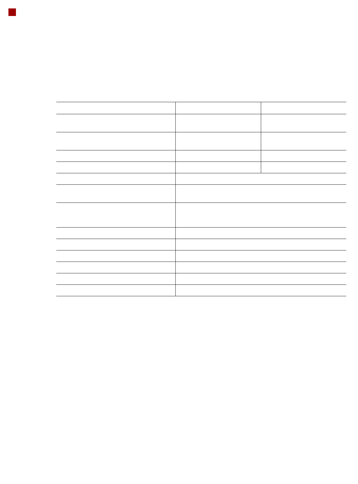
SIPLACE CA4 placement machine
a
a) Values only valid in conjunction with 4 X tables
See the note above for information about defining placement performance values.
Number of gantries 4
Placement area 1 Placement area 2 Benchmark value Option
C&P20 M / C&P20 M C&P20 M / C&P20 M 80,000
Without High Precision Flag
C&P20 M / C&P20 M C&P20 M / C&P20 M 64,000 With High Precision Flag
C&P20 M / C&P20 M CPP_H / CPP_H 76,000 Without High Precision Flag
C&P20 M / C&P20 M CPP_H / CPP_H 67,000 With High Precision Flag on
C&P20 M
CPP_H / CPP_H CPP_H / CPP_H 72,000 --
C&P20 M / C&P20 M CPP_H / TH 63,000 Without High Precision Flag
C&P20 M / C&P20 M CPP_H / TH 54,000 With High Precision Flag on
C&P20 M
CPP_H / CPP_H CPP_H / TH 59,000 --

9
Machine Description
Technical Data - SMT
Number of gan-
tries
CA4: 4 gantries
Component feed-
ing
– SIPLACE CA4: Up to four SWS possible in placement area 1 and 2
– Component trolley (X-Series)
(with tape reel mount and integrated waste tape bin,
40 locations à 8 mm X feeder module per component trolley)
– Matrix Tray Changer (on request)
Feeder module
types
– X-Series component trolley: Tapes, waffle pack trays
Supply capacity
(X-Series compo-
nent trolley)
160 tracks Width: 10.8 mm 4 mm X feeder modules
160 tracks Width: 10.8 mm 8 mm X feeder modules
160 tracks Width: 22.9 mm Smart Feeder 2x8 mm X
80 tracks Width: 22.6 mm Smart Feeder 12 mm X
52 tracks Width: 22.6 mm Smart Feeder 16 mm X
52 tracks Width: 34.4 mm 24 mm X feeder modules
40 tracks Width: 46.2 mm 32 mm X feeder modules
32 tracks Width: 58.0 mm 44 mm X feeder modules
24 tracks Width: 69.8 mm 56 mm X feeder modules
20 tracks Width 81.6 mm 72 mm X feeder modules
16 tracks Width: 105.2 mm 88 mm X feeder modules
10
Machine Description
Technical Data - SWS
Technical Data Flip Chip Die Attach
Minimum die thickness (silicium) - without com-
ponent sensor
50 µm 50 µm
Minimum die thickness (silicium) - with compo-
nent sensor
100 µm 100 µm
Minimum bump size 50 µm n/a
Minimum bump grid 100 µm n/a
SIPLACE Wafer System SWS Horizontal system, automatic wafer change, MCM
SWS wafer size 4" to 12"
4" / 6" with adapter on request
Wafer frame 12“/8“
6" on request
4" with adapter
Hoop /grip ring thickness Max. 3.5 mm
Wafer magazine
a
a) Depending on the wafer magazine, you may need to mechanically adjust the base plate for the wafer magazines.
Up to 12"
Die Ejection System Programmable ejection speed (synchronous and asynchronous)
Option: Linear Dipping Unit LDU Individually programmable speed
Flux viscosity 3,000 to 100,000 cPs
Accuracy of flux height ± 5 µm