Spec of AX-3 AX-5 June 2005 LR - 第10页
The pick and place module of the AX has three sub modules: the placement robot, the placement controller and the placement head. The AX can be equipped with two types of placement robots or a mix of the two; the standard…
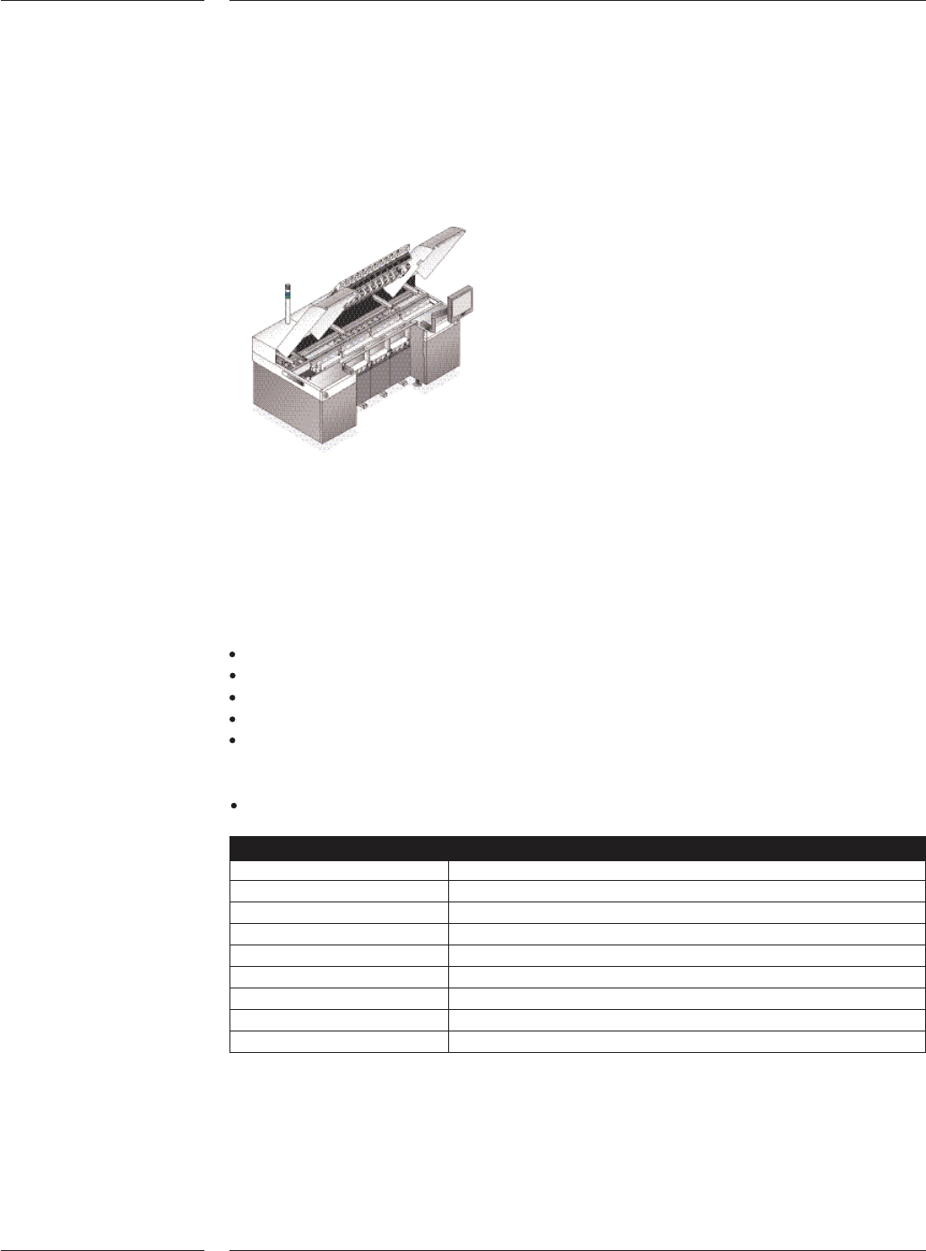
The AX Base contains a board transport unit, run-in section, where boards from the
previous machine are received, and a run-out section, where boards are transferred to the
next machine. The trolley lift is integrated in the front side of the base. At the rear side of
the base the placement controllers are located which control placement robots and place-
ment heads.
Machine base
The AX Transport feeds the boards from the run-in section to the run-out section in a
number of steps. After each step, the placement robots will place components on all the
boards in the transport area.
AX Transport specifics:
Edge clamp walking beam
Automatic width adjust
Automatic board thickness adjust
Automatic run-in board stopper adjust
Easy maintenance
Board support
Pins or strips with magnetic interface
Base and transport
Board dimensions L x W Min. 50 x 50mm, 50 x 25mm optional
Max. 475 x 390mm, 475 x 457mm optional (AX-3)
Max. 515 x 390mm, 515 x 457mm optional (AX-5)
Board thickness 0.3mm - 6mm. Optional other transport systems are
available like 11 mm for boats
Board weight Max. 2 kg.
Board transport Standard left to right
Optional right to left
Board transport height SMEMA and Japanese
2.3 AX Base
Figure 1
Features
7 of 34
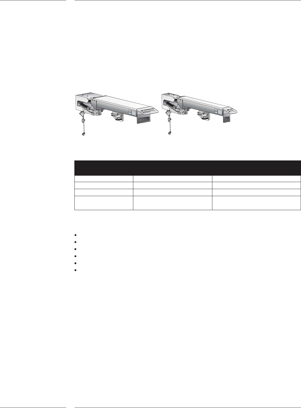
The pick and place module of the AX has three sub modules: the placement robot,
the placement controller and the placement head. The AX can be equipped with two
types of placement robots or a mix of the two; the standard placement robot and
the compact placement robot. Both placement robots use the same hardware and
software and achieve the same specifications. A compact placement robot is half
the width of a standard placement robot. This allows scaling the AX platform in out-
put while maintaining the available feeding positions.
Standard placement robot and compact placement robot
Standard placement Compact placement
robot robot
Working area 200 x 590mm 80 x 590mm
Weight 52 kg 32 kg
Dimensions (LxWxH) 1625 x 240 x 250mm 1625 x 120 x 250mm
Max. number of
partnumbers 26 11
Placement robot specifics:
Direct drive Y spindle using high-resolution rotary encoders
Linear X motor and encoder
Placement head interface
Safety interlocks
Quick exchange connection cables to placement controller
Air controller and local vacuum system (venturi)
2.4 Placement
robot
Figure 2
Contents
8 of 34
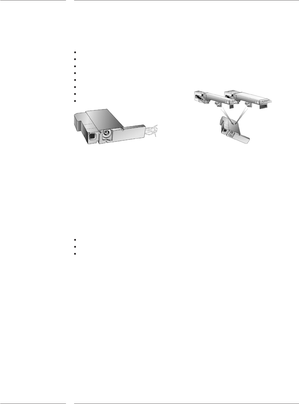
Each placement robot is fitted with a placement head. The placement head
executes the following tasks:
Z-movement
Rz-movement
Component alignment
Board alignment
Force sensing and control
Trolley and feeder detection
Toolbit exchange unit detection
Board warpage correction
Placement head
The Z-stroke uses a linear motor. This linear motor controls the pickup force,
placement Z-speed and placement dwell and impact force.
Board warpage correction
When a board enters the placement area, every placement head measures the
impact position and calculates the appropriate Z-height to correct for any applicable
board warpage. This adaptive Z-height feature enables that the appropriate
placement dwell force and impact force is well within the tolerance of process
requirements.
AX Placement head force specifications
Placement force range 2N to 8N, lower forces with restrictions
Programmable placement force stepsize 0.1N
Placement force control by linear motor current servo loop
2.5 Placement
head
Figure 3
Contents
9 of 34