Spec of AX-3 AX-5 June 2005 LR - 第30页
Placement per robot Component size 0.4 x 0.2mm (01005) to 45 x 45mm Component height 6.3mm: (LxW: < 24 x 24mm) 4.3mm: (LxW: > 24 x 24mm and < 45 x 45mm) 10.75mm with restrictions Component types 01005-2518, SOIC…
4 Technical
specifications
4.1 Configurable
placement
output
Features
27 of 34
The AX is configurable in output using two different placement robots. The specifi-
cations on placement output are based on four different configurations for the
AX Platform using either only standard placement robots, only compact placement
robots or a combination of both.
The output is based on the test procedure of IPC9850 whereby is specified the
type of board used, its size & thickness, the amount of components to be placed
and each placement location.
The IPC9850 specifies also that the accuracy data is linked with the speed per-
formance data. The IPC9850 is developed to provide a transparent comparison
methodology for speed and accuracy specifications between different Vendors.
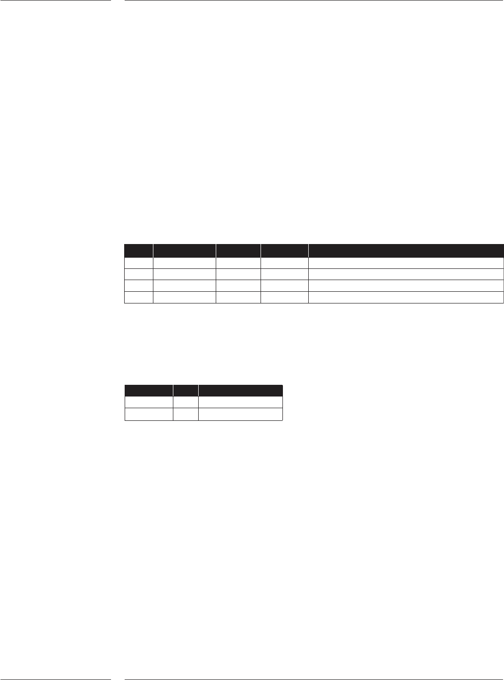
Conf AX Base CPR SPR IPC9850 output
A Base-3 0 6 33K
B Base-3 12 0 61K
C Base-5 0 10 50K
D Base-5 20 0 94.3K
SPR = Standard placement robot, CPR = Compact placement robot
For the AX Platform the following output figures can be achieved with an ideal
application.
AX Base CPR Optimal output
Base-3 12 90K
Base-5 20 135K
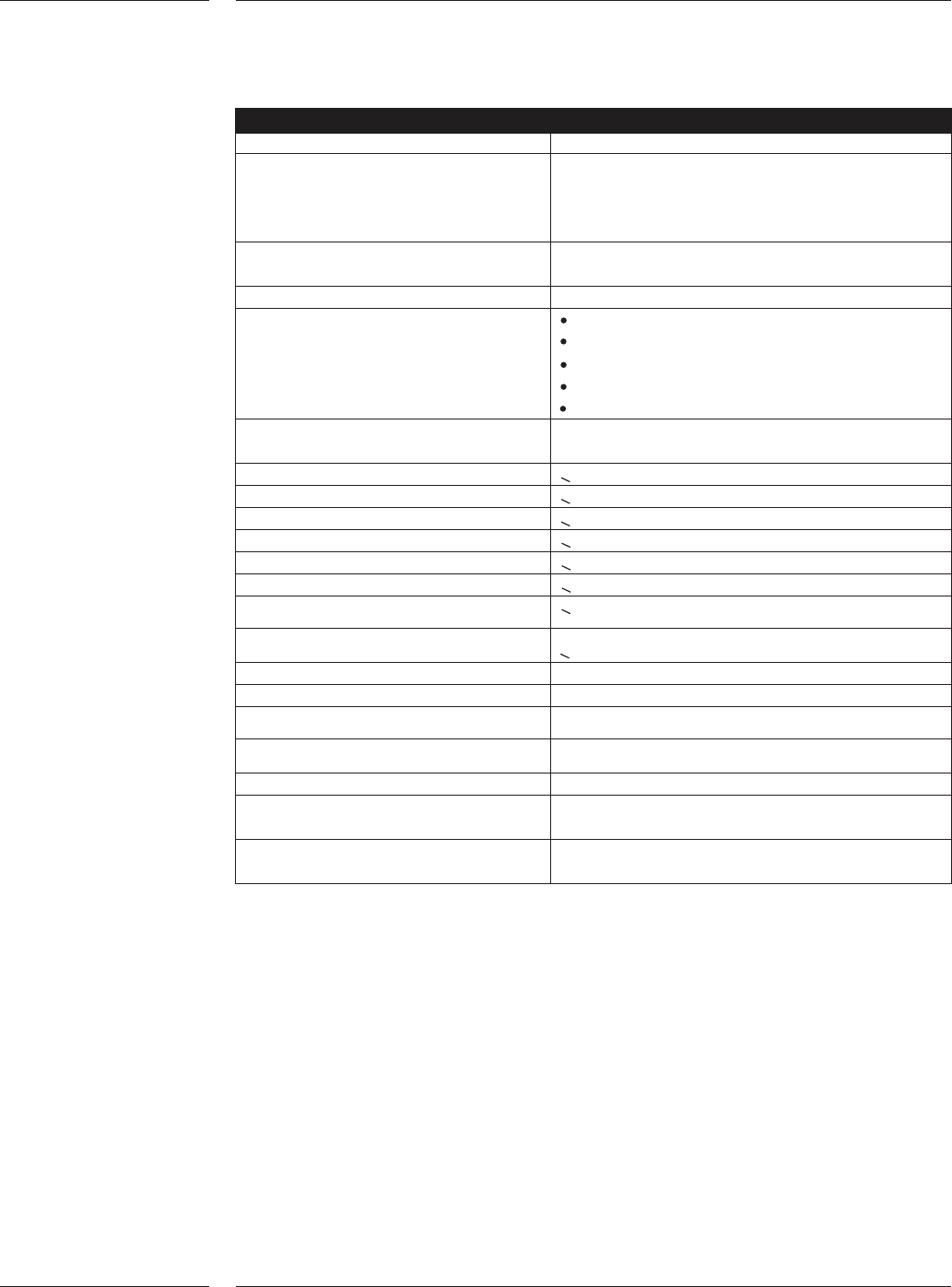
Placement per robot
Component size 0.4 x 0.2mm (01005) to 45 x 45mm
Component height 6.3mm: (LxW: < 24 x 24mm)
4.3mm: (LxW: > 24 x 24mm
and < 45 x 45mm)
10.75mm with restrictions
Component types 01005-2518, SOIC, melfs, SOTs, SOD, PLCC,
QFP, BGA, µBGA, CSP etc.
Component alignment principle Laser alignment & CCD Vision
Component sensing Component presence
Component absence
Component offset
Component dimensions
Component shape
Max. number of components per 1500 / Robot
board
Speed X direction <0.5 m/s
Speed Y direction <1.4 m/s
Speed Rz direction <10 rev/sec
Speed Z direction <0.5 m/s
Acceleration X direction <5 m/s2
Acceleration Y direction <16 m/s2
Acceleration R
z
direction <300 rev/ s2
Acceleration Z direction <40 m/s2
Encoder measurement resolution X 0.5µm
Encoder measurement resolution Y 1.5µm
Encoder measurement resolution R
z
0.31 mrad
Encoder measurement resolution Z 5µm
Component Vision Field of view 67,8 x 50.5mm
Component Vision CCD Array 1280 x 960 pixels
resolution
Placement force 2-8N programmable in steps of 0.1N
Lower forces with restrictions
4.2 Placement
specifications
Features
28 of 34

Components and packaging
R, C, MELF, SOT, SOD, SO, 0.4 x 0.2mm (01005) to 45x45mm
PLCC, QFP, BGA's,
µ
BGA 's,
SSOP, Odd SMD and round
components
Height Minimum: 0.15mm
Maximum:
24 x 24mm = 6.3mm
24 x 24mm - 45 x 45mm = 4.3mm
10.75mm with restrictions
Lead pitch < 0.4mm (0.016")
Lead width < 0.2mm (0.008")
Min. Bump size / pitch 0.15mm (0.006") / 0.3mm (0.012") for
components up to 12 x 12mm
0.3mm (0.012") / 0.5mm (0.020") for
components > 12 x 12mm
Number of bumps Min: 2, max: 3500
Component pick orientation Multiples of 90 degrees
Component pick offset < 0.5mm w.r.t. tape (IEC286-3)
Weight < 12g
Tape sizes 8-56mm wide (IEC286-3)
Reel diameters Up to 330mm (13") for standard single lane ITF
(optional 15" and 22")
Bulk C 0.6 x 0.3mm up to 2.0 x 1.25mm
Bulk R 1.0 x 0.5mm up to 2.0 x 1.25mm
Melf: 1.5 x 1.0mm, 2.0 x 1.25mm
4.3 Components
and
packaging
Features
29 of 34