Spec of AX-3 AX-5 June 2005 LR - 第31页
Components and packaging R, C, MELF, SOT, SOD, SO, 0.4 x 0.2mm (01005) to 45x45mm PLCC, QFP, BGA's, µ BGA 's, SSOP, Odd SMD and round components Height Minimum: 0.15mm Maximum: 24 x 24mm = 6.3mm 24 x 24mm - 45 …
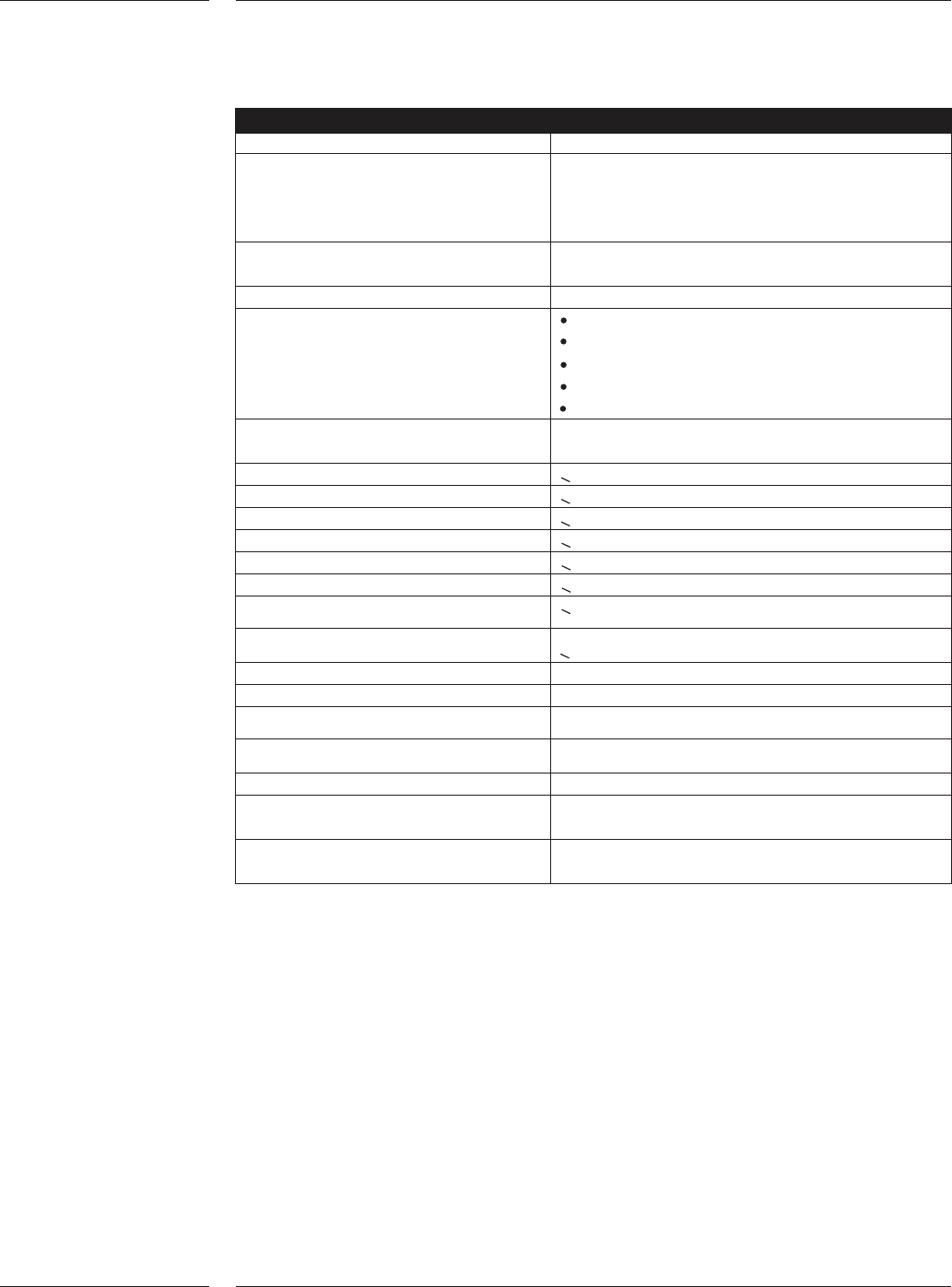
Placement per robot
Component size 0.4 x 0.2mm (01005) to 45 x 45mm
Component height 6.3mm: (LxW: < 24 x 24mm)
4.3mm: (LxW: > 24 x 24mm
and < 45 x 45mm)
10.75mm with restrictions
Component types 01005-2518, SOIC, melfs, SOTs, SOD, PLCC,
QFP, BGA, µBGA, CSP etc.
Component alignment principle Laser alignment & CCD Vision
Component sensing Component presence
Component absence
Component offset
Component dimensions
Component shape
Max. number of components per 1500 / Robot
board
Speed X direction <0.5 m/s
Speed Y direction <1.4 m/s
Speed Rz direction <10 rev/sec
Speed Z direction <0.5 m/s
Acceleration X direction <5 m/s2
Acceleration Y direction <16 m/s2
Acceleration R
z
direction <300 rev/ s2
Acceleration Z direction <40 m/s2
Encoder measurement resolution X 0.5µm
Encoder measurement resolution Y 1.5µm
Encoder measurement resolution R
z
0.31 mrad
Encoder measurement resolution Z 5µm
Component Vision Field of view 67,8 x 50.5mm
Component Vision CCD Array 1280 x 960 pixels
resolution
Placement force 2-8N programmable in steps of 0.1N
Lower forces with restrictions
4.2 Placement
specifications
Features
28 of 34
Components and packaging
R, C, MELF, SOT, SOD, SO, 0.4 x 0.2mm (01005) to 45x45mm
PLCC, QFP, BGA's,
µ
BGA 's,
SSOP, Odd SMD and round
components
Height Minimum: 0.15mm
Maximum:
24 x 24mm = 6.3mm
24 x 24mm - 45 x 45mm = 4.3mm
10.75mm with restrictions
Lead pitch < 0.4mm (0.016")
Lead width < 0.2mm (0.008")
Min. Bump size / pitch 0.15mm (0.006") / 0.3mm (0.012") for
components up to 12 x 12mm
0.3mm (0.012") / 0.5mm (0.020") for
components > 12 x 12mm
Number of bumps Min: 2, max: 3500
Component pick orientation Multiples of 90 degrees
Component pick offset < 0.5mm w.r.t. tape (IEC286-3)
Weight < 12g
Tape sizes 8-56mm wide (IEC286-3)
Reel diameters Up to 330mm (13") for standard single lane ITF
(optional 15" and 22")
Bulk C 0.6 x 0.3mm up to 2.0 x 1.25mm
Bulk R 1.0 x 0.5mm up to 2.0 x 1.25mm
Melf: 1.5 x 1.0mm, 2.0 x 1.25mm
4.3 Components
and
packaging
Features
29 of 34

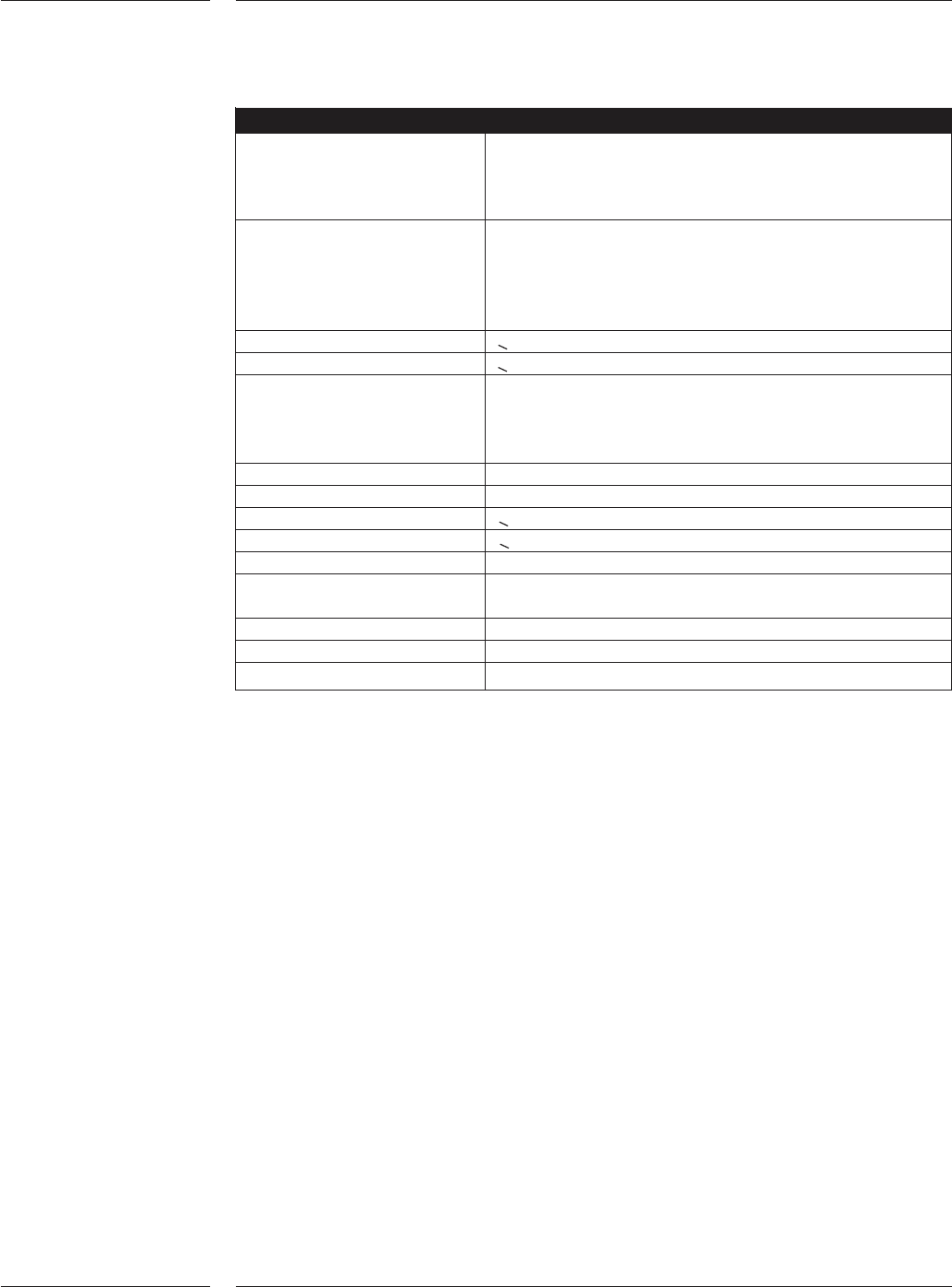
Circuit board
Board material Phenolic/paper (FR2)
Glass-Epoxy (FR4)
Composite materials
IPC 9850 Glass verification panel
Optionally:
Ceramics
Auer carriers
Flex foil
Board artwork material / Hot Air Solder Leveled (HASL)
surface finish Bare copper with OSP
Electroless Ni / Immersion AU
Board range min (L x W) 50 x 50mm (L = Board transport direction)
50 x 25mm optional
Board range max (L x W) AX-3 : 475 x 390mm
(L = Board transport direction)
475 x 457mm optional
AX-5 : 515 x 390mm
(L = Board transport direction)
515 x 457mm optional
Y/X ratio < 2.5
Board thickness 0.3 - 6mm. Optional other transport systems are
available like 11 mm for boats
Pre-mounted components Max. 20mm bottomside, max. 6.3mm topside
Warpage (Flatness) Topside: Max. 0.6% of diagonal to max +2mm
Bottomside: Max. -2mm (due to board weight)
Edge clearance 3mm from front and rear edge of board
Board weight < 2 kg
Transport direction Standard left to right
Optional right to left
4.4 Board
specifications
Features
30 of 34