Spec of AX-3 AX-5 June 2005 LR - 第9页
The AX Base contains a board transport unit, run-in section, where boards from the previous machine are received, and a run-out section, where boards are transferred to the next machine. The trolley lift is integrated in…
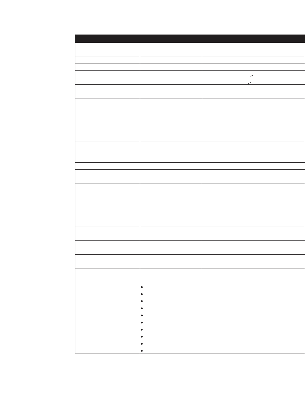
2.2 AX-5
Specifications
Features
6 of 34
AX-5 Main specification
Max output [CpH] 150.000 20 Compact placement robots
Max output [CpH] 75.000 10 Standard placement robots
IPC 9850 [CpH] 94.300 20 Compact placement robots
IPC 9850 [CpH] 50.000 10 Standard placement robots
Highest Accuracy class 50µm µ+4 sigma (Cpk>1.33)
40µm µ+3 sigma (Cpk>1.00)
0201 interspacing 100µm Smaller interspacing possible with
restrictions
Pick performance 99,87 % Automatic
*1
99,995 % Manual
*1
Placement quality < 20 PPM
Technical Uptime > 99.4% (Based on AX-5 with 10 placement
robots and excl feeder assists)
Lifetime nozzle 2-4 Mio placements (depending on type)
Component range SMD components 0.4 x 0.2mm (01005) to 45 x 45mm
Feeding positions 260 Use twin tape feeders
[# x 8mm] 260 Twinbulk feeders
130 Single tape feeders
Feeding types (Twin-) tape, (twin-) bulk
Placement force 2N to 8N, lower forces Programmable in stepsizes of 0.1N
with restrictions
Board range min (L x W) 50 x 50mm L = Board transport direction
50 x 25mm optional
Board range max (L x W)515 x 390mm L = Board transport direction
515 x 457mm optional
Board transport directionStandard left to right
Optional right to left
Power supply 200-480V 3-phase
47-63Hz, 7 kVA
Air supply 6-8 bar, 230Nl/min (Tape feeding only)
6-8 bar, 290Nl/min (Tape & Bulk feeding)
Dimensions 3720x2285x1290mm Total 8.5 m2
(incl. trolleys) (LxWxH)
Weight (excl trolleys) <3200kg
Noise 72 dB(A) @ 1m distance
Applicable standards : 98/37/EC CE Machine directive
89/336/EEC CE EMC directive
73/23/EEC CE Low voltage directive
CSA/UL
SEMI S2 Safety standard
SEMI S8 Ergonomics standard
SEMI E10 RAM
SEMI E58 ARAM
SEMI E95 Human Interfaces standard
IPC 9850 Accuracy & speed testing standard
*1
: Based on feeders smaller than 24mm, excluding 01005 components.
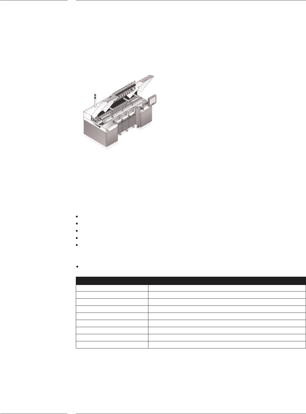
The AX Base contains a board transport unit, run-in section, where boards from the
previous machine are received, and a run-out section, where boards are transferred to the
next machine. The trolley lift is integrated in the front side of the base. At the rear side of
the base the placement controllers are located which control placement robots and place-
ment heads.
Machine base
The AX Transport feeds the boards from the run-in section to the run-out section in a
number of steps. After each step, the placement robots will place components on all the
boards in the transport area.
AX Transport specifics:
Edge clamp walking beam
Automatic width adjust
Automatic board thickness adjust
Automatic run-in board stopper adjust
Easy maintenance
Board support
Pins or strips with magnetic interface
Base and transport
Board dimensions L x W Min. 50 x 50mm, 50 x 25mm optional
Max. 475 x 390mm, 475 x 457mm optional (AX-3)
Max. 515 x 390mm, 515 x 457mm optional (AX-5)
Board thickness 0.3mm - 6mm. Optional other transport systems are
available like 11 mm for boats
Board weight Max. 2 kg.
Board transport Standard left to right
Optional right to left
Board transport height SMEMA and Japanese
2.3 AX Base
Figure 1
Features
7 of 34
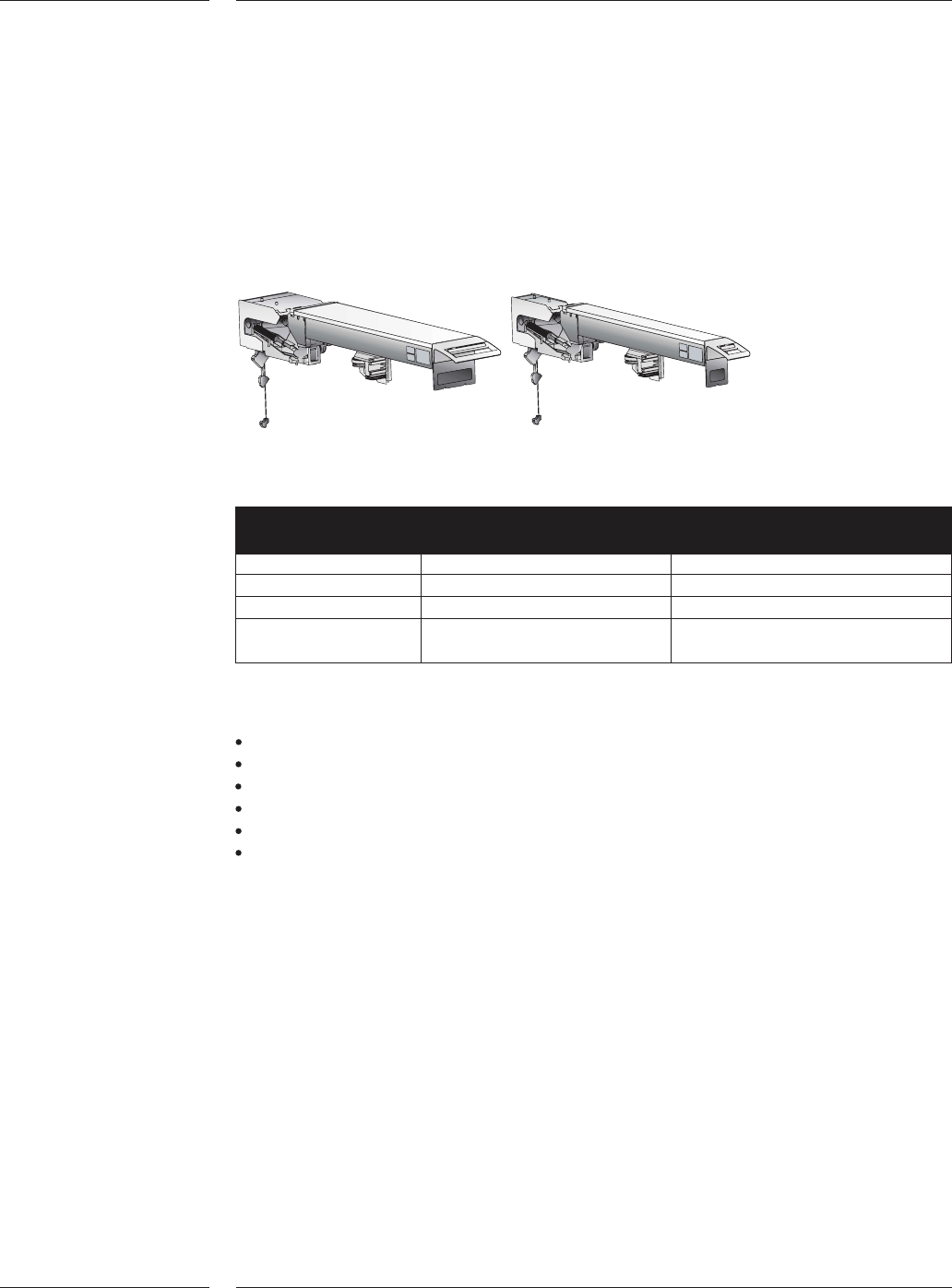
The pick and place module of the AX has three sub modules: the placement robot,
the placement controller and the placement head. The AX can be equipped with two
types of placement robots or a mix of the two; the standard placement robot and
the compact placement robot. Both placement robots use the same hardware and
software and achieve the same specifications. A compact placement robot is half
the width of a standard placement robot. This allows scaling the AX platform in out-
put while maintaining the available feeding positions.
Standard placement robot and compact placement robot
Standard placement Compact placement
robot robot
Working area 200 x 590mm 80 x 590mm
Weight 52 kg 32 kg
Dimensions (LxWxH) 1625 x 240 x 250mm 1625 x 120 x 250mm
Max. number of
partnumbers 26 11
Placement robot specifics:
Direct drive Y spindle using high-resolution rotary encoders
Linear X motor and encoder
Placement head interface
Safety interlocks
Quick exchange connection cables to placement controller
Air controller and local vacuum system (venturi)
2.4 Placement
robot
Figure 2
Contents
8 of 34