Spectrum Operating Manual - 第132页
S2-9 XX X Se ri es Disp ensi n g Syst em IOM Man ual Maintenance 6-20 © 2023 Nordson Corporatio n 6.12 Adjus ting the Linear Encoders To ols and Mater ials Neede d: • 0.8 mm G auge (included with li nea r encoder) • Thre…
S2-9XXX Series Dispensing System IOM Manual Maintenance
© 2023 Nordson Corporation 6-19
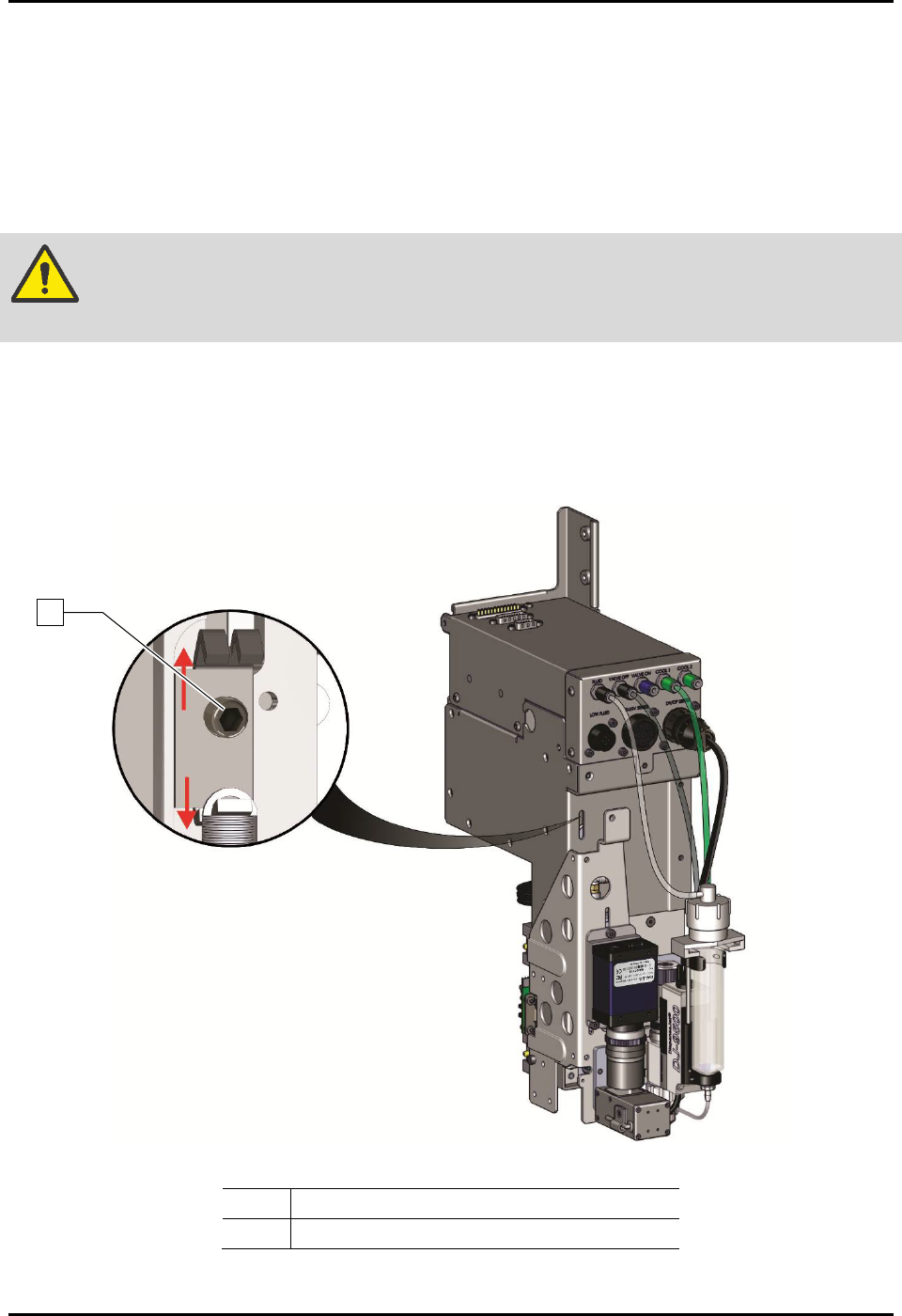
6.11.2 Tensioning the Z Cable
To tension the Z cable (Figure 6-12):
1. Perform a service shutdown, see 2.14 Service Shutdown.
2. Open the dispensing area door.
3. Use an M3 hex key to loosen (one turn) the tensioner screw.
WARNING! DO NOT remove the tensioner screw. If removed, the entire Z-head must be
disassembled.
4. Manually move the dispensing head up and down the full length of the axis. Repeat
three (3) to five (5) times.
5. Tighten the tensioner screw.
6. Close the dispensing area door.
Item
Description
1
Tensioner Screw
Figure 6-12 Tensioning the Z-Axis Cables
1
S2-9XXX Series Dispensing System IOM Manual Maintenance
6-20 © 2023 Nordson Corporation
6.12 Adjusting the Linear Encoders
Tools and Materials Needed:
• 0.8 mm Gauge (included with linear encoder)
• Thread Locker
•
3 mm Hex Key
• Torque Wrench 0-100 in-lbs
6.12.1 Adjusting the X-Axis Linear Encoder
To adjust the X-axis linear encoder
1. If necessary, power on the dispensing system, see 4.3 Powering on the Dispensing System.
2. Exit Fluidmove.
3. Open the dispensing area door.
4. Verify that the light beacon is yellow and that all axes move freely by hand.
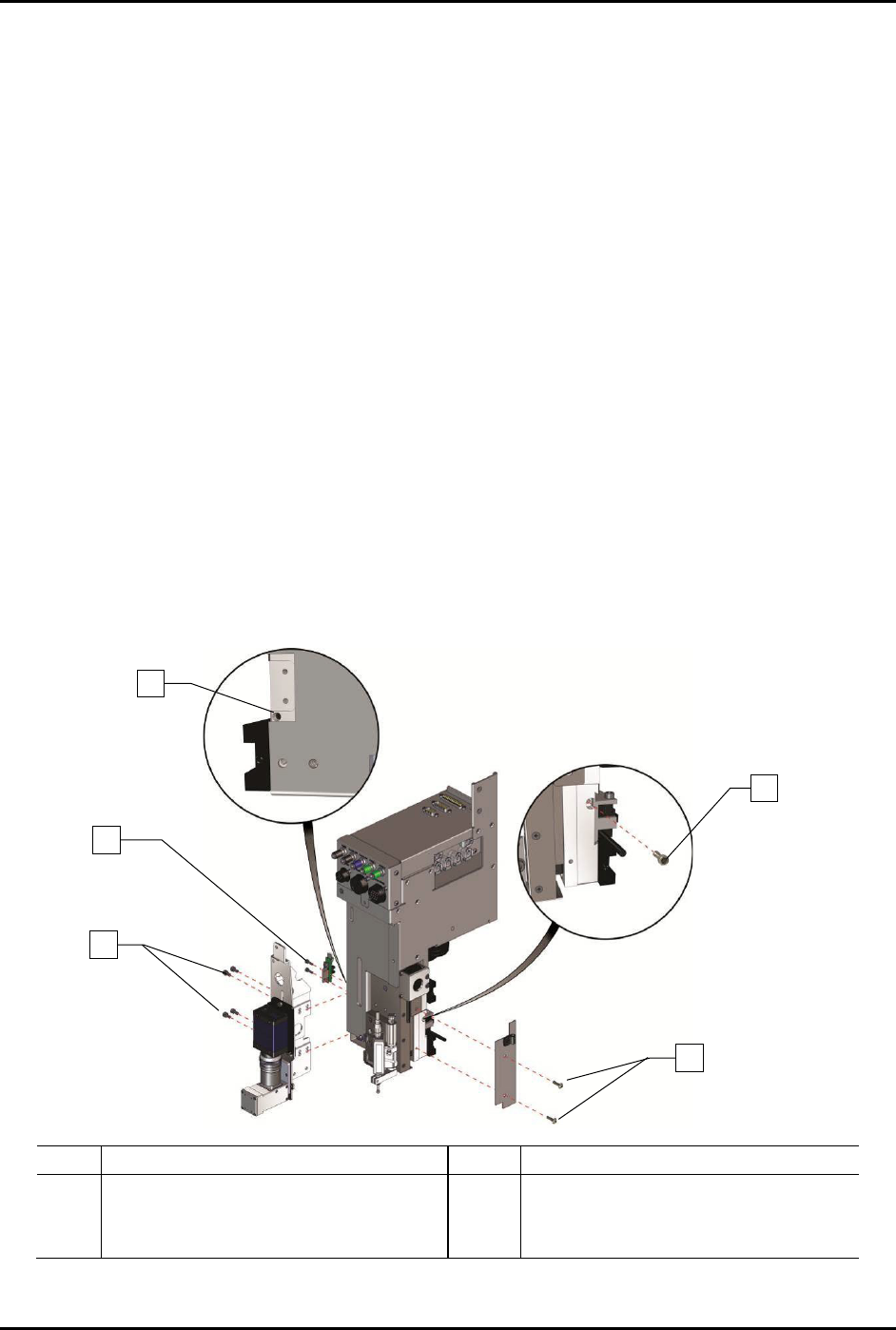
5. To gain access to the X-axis linear encoder (Figure 6-13):
a. Use a 3 mm hex key to remove the four (4) screws on the camera bracket, two (2)
Z-head home switch screws, and two (2) Z-head panel screws.
b. Remove one (1) encoder mounting bracket screw securing the encoder mounting
bracket to the Z-head.
In order to remove the encoder mounting bracket screw, you will need to install and
tighten one (1) M4 setscrew on the left of the Z-head below the on-switch.
Item
Description
Item
Description
1
M-4 Setscrew
4
Encoder Mounting Bracket Screw
2
Z-Head Home Switch Screws (2)
5
Z-Head Panel Screws (2)
3
Camera Bracket Screws (4)
Figure 6-13 Accessing the Linear Encoder
1
3
4
5
2
S2-9XXX Series Dispensing System IOM Manual Maintenance
© 2023 Nordson Corporation 6-21
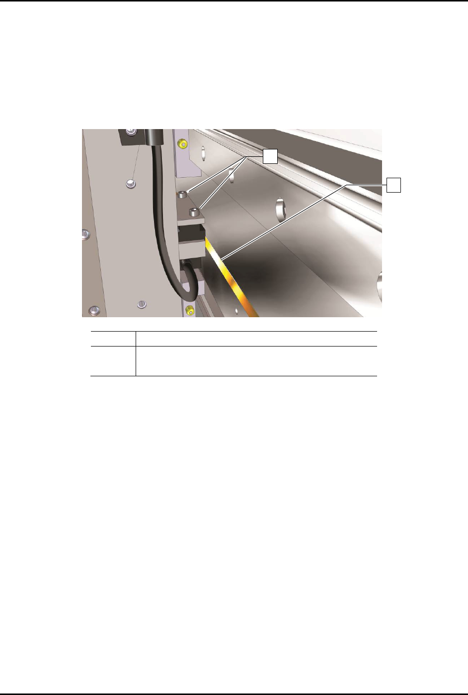
6. With the X-axis linear encoder and mounting bracket removed, lay the mounting bracket on
a flat surface with the sensor window facing down.
7. Loosen the two (2) read head mounting screws securing the linear encoder head in the
bracket (Figure 6-14).
8. Lower the linear encoder head and rest the linear encoder head against the flat surface.
9. Tighten the two (2) read head mounting screws to secure the head in that position (flush
against the flat surface).
-
Item
Description
1
Read Head Mounting Screws
2 Linear Encoder
Figure 6-14 X-Axis Encoder Read Head Mounting Screws
10. Reinstall the linear encoder and mounting bracket.
11. Tighten the two (2) read head mounting screws to secure the encoder in place.
12. Reinstall the two (2) Z-head panel screws and camera bracket screws.
13. Manually move the dispensing head left and right and make sure that the encoder LED
remains green when in motion.
If the LED turns red or orange when the axis is in motion, repeat Step 6 through Step 12
and adjust the encoder height again.
If the LED turns red or orange in a specific location, it may be due to an obstruction or
a damaged encoder strip. Use a soft cloth and mild cleanser to clean that location. If the
problem is not resolved, repeat Step 6 through Step 12 and adjust the encoder height
again.
14. When the LED stays green throughout the entire dispensing head travel, close the
dispensing area door and restart Fluidmove.
15. Observe the dispensing head motion to ensure the dispensing head initializes and finds
home correctly.
1
2